


GASBOY Series 9800A
5-2
03/07/03
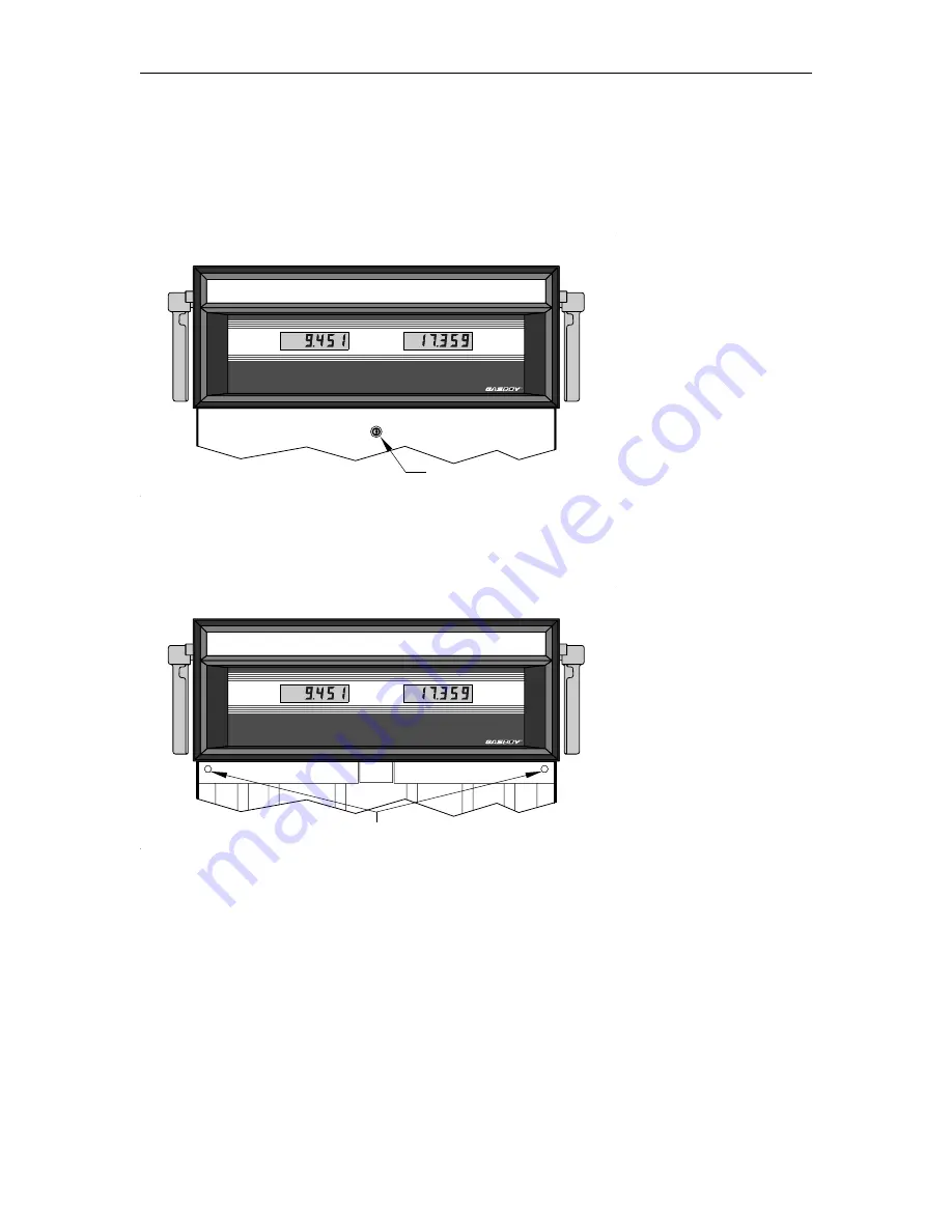
ELECTRONIC COMPONENT ACCESS
Before attempting to start-up the 9800A, it is important to become familiar with the location of
some key components as well as the various switch-selectable operating modes.
1.
Unlock and remove the front panel.
2.
Remove the two bolts located over the tabs of the bezel assembly. Lift the bezel assembly
upwards and out to remove. If the model includes the front load nozzle, remove the nozzle
boot plastic shroud (two screws) before removing the bezel assembly.
3.
Loosen, and remove if necessary, the two screws located on the left and right door support
brackets and pivot display panel down.
UNLEADED
DIESEL
GALLONS
GALLONS
R
R
UNLOCK
UNLEADED
DIESEL
GALLONS
GALLONS
R
R
REMOVE
Summary of Contents for 9800A Series
Page 8: ......
Page 11: ...Chassis Wiring 03 07 03 2 3 115VAC 60 CYCLE PUMP WIRING...
Page 12: ...GASBOY Series 9800A 2 4 03 07 03 115VAC 60 CYCLE DISPENSER WIRING...
Page 13: ...Chassis Wiring 03 07 03 2 5 230VAC 50 CYCLE PUMP WIRING...
Page 14: ...GASBOY Series 9800A 2 6 03 07 03 230VAC 50 CYCLE DISPENSER WIRING...
Page 15: ...Chassis Wiring 03 07 03 2 7 115VAC 60 CYCLE FRONT LOAD OPTION PUMP WIRING...
Page 16: ...GASBOY Series 9800A 2 8 03 07 03 115VAC 60 CYCLE FRONT LOAD OPTION DISPENSER WIRING...
Page 17: ...Chassis Wiring 03 07 03 2 9 230VAC 50 CYCLE FRONT LOAD OPTION PUMP WIRING...
Page 18: ...GASBOY Series 9800A 2 10 03 07 03 230VAC 50 CYCLE FRONT LOAD OPTION DISPENSER WIRING...
Page 19: ...Chassis Wiring 03 07 03 2 11...
Page 20: ......
Page 39: ...Electronic Head Assembly 03 07 03 3 19 Connectors Relay Drive Pump Motor Power...
Page 60: ......
Page 65: ...Replacement Instructions 03 07 03 5 5...
Page 72: ...GASBOY Series 9800A 5 12 03 07 03...
Page 75: ......
Page 76: ...APPENDIX PARTS LIST...
Page 77: ......


