


Electronic
Head
Assembly
03/07/03
3-5
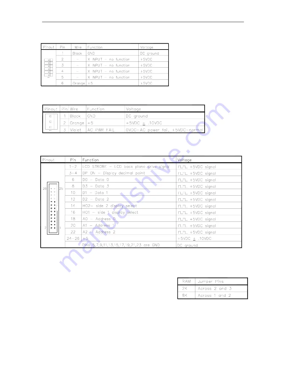
P9 – Front Load Option
P10 - Power Supply Input
P11 - LCD Display Interface
Jumpers
Jumper K1 is set according to the size of the RAM IC in
socket U19.
The 9800A CPU PCB can accommodate two sizes of battery-
backed RAM; 2K and 8K. At this time only the 2K size is
being used.
Summary of Contents for 9800A Series
Page 8: ......
Page 11: ...Chassis Wiring 03 07 03 2 3 115VAC 60 CYCLE PUMP WIRING...
Page 12: ...GASBOY Series 9800A 2 4 03 07 03 115VAC 60 CYCLE DISPENSER WIRING...
Page 13: ...Chassis Wiring 03 07 03 2 5 230VAC 50 CYCLE PUMP WIRING...
Page 14: ...GASBOY Series 9800A 2 6 03 07 03 230VAC 50 CYCLE DISPENSER WIRING...
Page 15: ...Chassis Wiring 03 07 03 2 7 115VAC 60 CYCLE FRONT LOAD OPTION PUMP WIRING...
Page 16: ...GASBOY Series 9800A 2 8 03 07 03 115VAC 60 CYCLE FRONT LOAD OPTION DISPENSER WIRING...
Page 17: ...Chassis Wiring 03 07 03 2 9 230VAC 50 CYCLE FRONT LOAD OPTION PUMP WIRING...
Page 18: ...GASBOY Series 9800A 2 10 03 07 03 230VAC 50 CYCLE FRONT LOAD OPTION DISPENSER WIRING...
Page 19: ...Chassis Wiring 03 07 03 2 11...
Page 20: ......
Page 39: ...Electronic Head Assembly 03 07 03 3 19 Connectors Relay Drive Pump Motor Power...
Page 60: ......
Page 65: ...Replacement Instructions 03 07 03 5 5...
Page 72: ...GASBOY Series 9800A 5 12 03 07 03...
Page 75: ......
Page 76: ...APPENDIX PARTS LIST...
Page 77: ......


