GASBOY Series 9800A
3-10
03/07/03
Jumpers
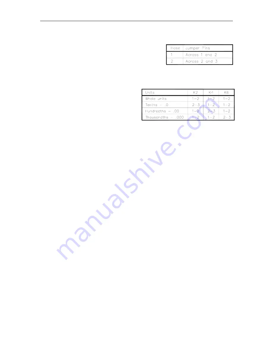
The LCD Display PCB must be addressed to display the
pump data for the hose (side) that is closest to it. This
means that two of the PCB’s are addressed as hose outlet
#1 and two are addressed as hose outlet #2 (in a twin).
Jumper K1 selects the display address.
The LCD Display PCB can be configured to
display whole units, tenths, hundredths, or
thousandths. Presently all domestic 9800A’s,
except 9850A, are shipped displaying
thousandths of a gallon; all international
9800A’s are shipped displaying hundredths.
9850A units are shipped displaying
hundredths. The 9850A liter software will
blank the hundredths location and display
tenths only. Jumper K2, K4, and K6 select the
units and their pins should be jumpered as
shown. Presently there is no software or
firmware to support whole units or tenths.
Summary of Contents for 9800A Series
Page 8: ......
Page 11: ...Chassis Wiring 03 07 03 2 3 115VAC 60 CYCLE PUMP WIRING...
Page 12: ...GASBOY Series 9800A 2 4 03 07 03 115VAC 60 CYCLE DISPENSER WIRING...
Page 13: ...Chassis Wiring 03 07 03 2 5 230VAC 50 CYCLE PUMP WIRING...
Page 14: ...GASBOY Series 9800A 2 6 03 07 03 230VAC 50 CYCLE DISPENSER WIRING...
Page 15: ...Chassis Wiring 03 07 03 2 7 115VAC 60 CYCLE FRONT LOAD OPTION PUMP WIRING...
Page 16: ...GASBOY Series 9800A 2 8 03 07 03 115VAC 60 CYCLE FRONT LOAD OPTION DISPENSER WIRING...
Page 17: ...Chassis Wiring 03 07 03 2 9 230VAC 50 CYCLE FRONT LOAD OPTION PUMP WIRING...
Page 18: ...GASBOY Series 9800A 2 10 03 07 03 230VAC 50 CYCLE FRONT LOAD OPTION DISPENSER WIRING...
Page 19: ...Chassis Wiring 03 07 03 2 11...
Page 20: ......
Page 39: ...Electronic Head Assembly 03 07 03 3 19 Connectors Relay Drive Pump Motor Power...
Page 60: ......
Page 65: ...Replacement Instructions 03 07 03 5 5...
Page 72: ...GASBOY Series 9800A 5 12 03 07 03...
Page 75: ......
Page 76: ...APPENDIX PARTS LIST...
Page 77: ......