GASBOY Series 9800A
5-14
03/07/03
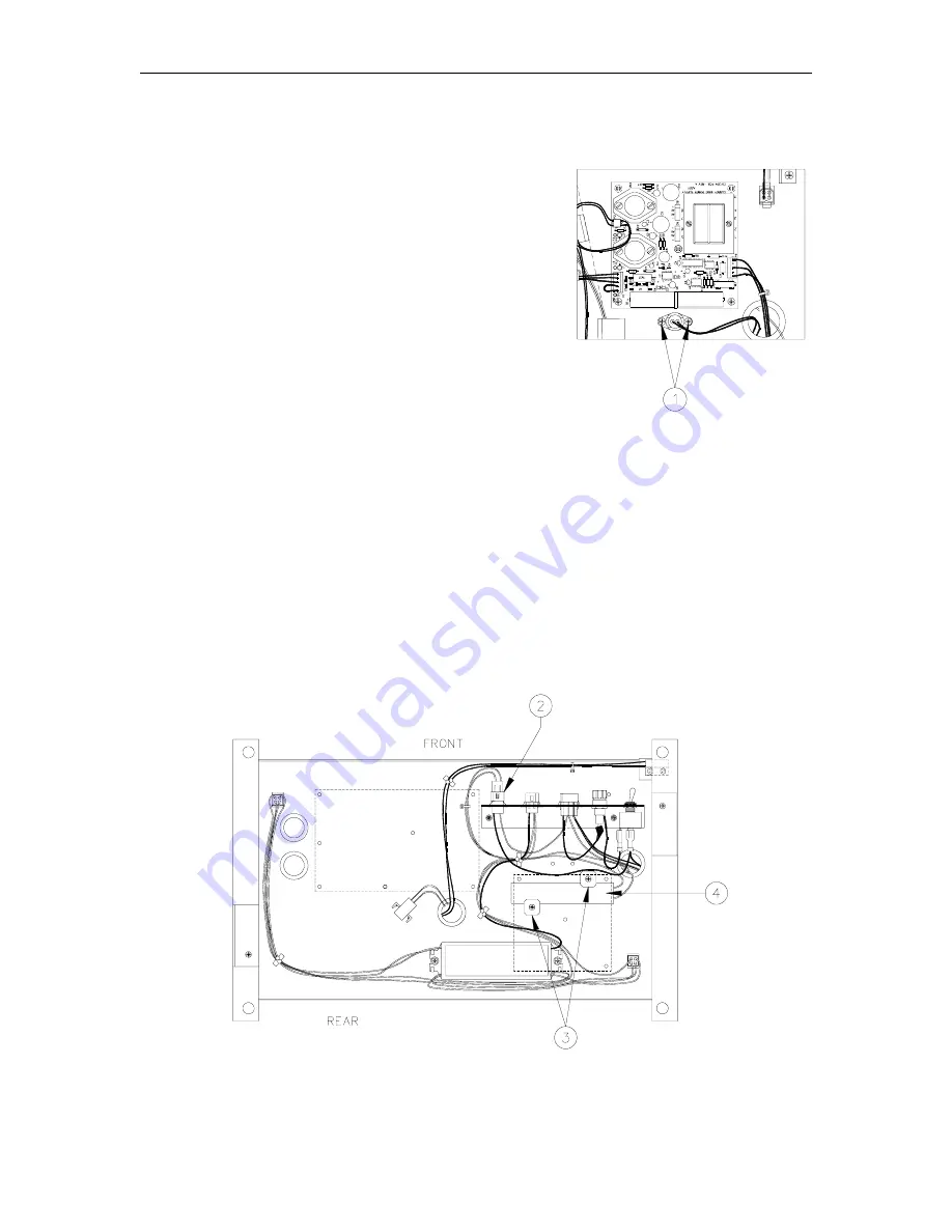
REPLACING THE HEATER CABLE ASSEMBLY
1.
The platform assembly must be removed in order to
replace the heater cable assembly. See Replacing
the Platform Assembly earlier in this section.
Proceed to Step 2 once platform assembly is
removed.
2. Remove the two Phillips screws [1] securing the
thermostat to the platform. Push the thermostat
through the bushing.
3.
Disconnect the HEATER connector [2] from the power bracket.
4.
Remove the two Phillips screws [3] and fiber washers retaining the heater strip.
5.
Peel the heater strip [4] from the platform.
6.
Remove backing from the new heater strip and secure it to the platform in the same position
as the old heater.
7.
Reverse Steps 2 through 4 to install the new heater cable assembly. See Replacing the
Platform Assembly earlier in this section to complete the procedure.
Summary of Contents for 9800A Series
Page 8: ......
Page 11: ...Chassis Wiring 03 07 03 2 3 115VAC 60 CYCLE PUMP WIRING...
Page 12: ...GASBOY Series 9800A 2 4 03 07 03 115VAC 60 CYCLE DISPENSER WIRING...
Page 13: ...Chassis Wiring 03 07 03 2 5 230VAC 50 CYCLE PUMP WIRING...
Page 14: ...GASBOY Series 9800A 2 6 03 07 03 230VAC 50 CYCLE DISPENSER WIRING...
Page 15: ...Chassis Wiring 03 07 03 2 7 115VAC 60 CYCLE FRONT LOAD OPTION PUMP WIRING...
Page 16: ...GASBOY Series 9800A 2 8 03 07 03 115VAC 60 CYCLE FRONT LOAD OPTION DISPENSER WIRING...
Page 17: ...Chassis Wiring 03 07 03 2 9 230VAC 50 CYCLE FRONT LOAD OPTION PUMP WIRING...
Page 18: ...GASBOY Series 9800A 2 10 03 07 03 230VAC 50 CYCLE FRONT LOAD OPTION DISPENSER WIRING...
Page 19: ...Chassis Wiring 03 07 03 2 11...
Page 20: ......
Page 39: ...Electronic Head Assembly 03 07 03 3 19 Connectors Relay Drive Pump Motor Power...
Page 60: ......
Page 65: ...Replacement Instructions 03 07 03 5 5...
Page 72: ...GASBOY Series 9800A 5 12 03 07 03...
Page 75: ......
Page 76: ...APPENDIX PARTS LIST...
Page 77: ......