


GASBOY Series 9800A
5-10
03/07/03
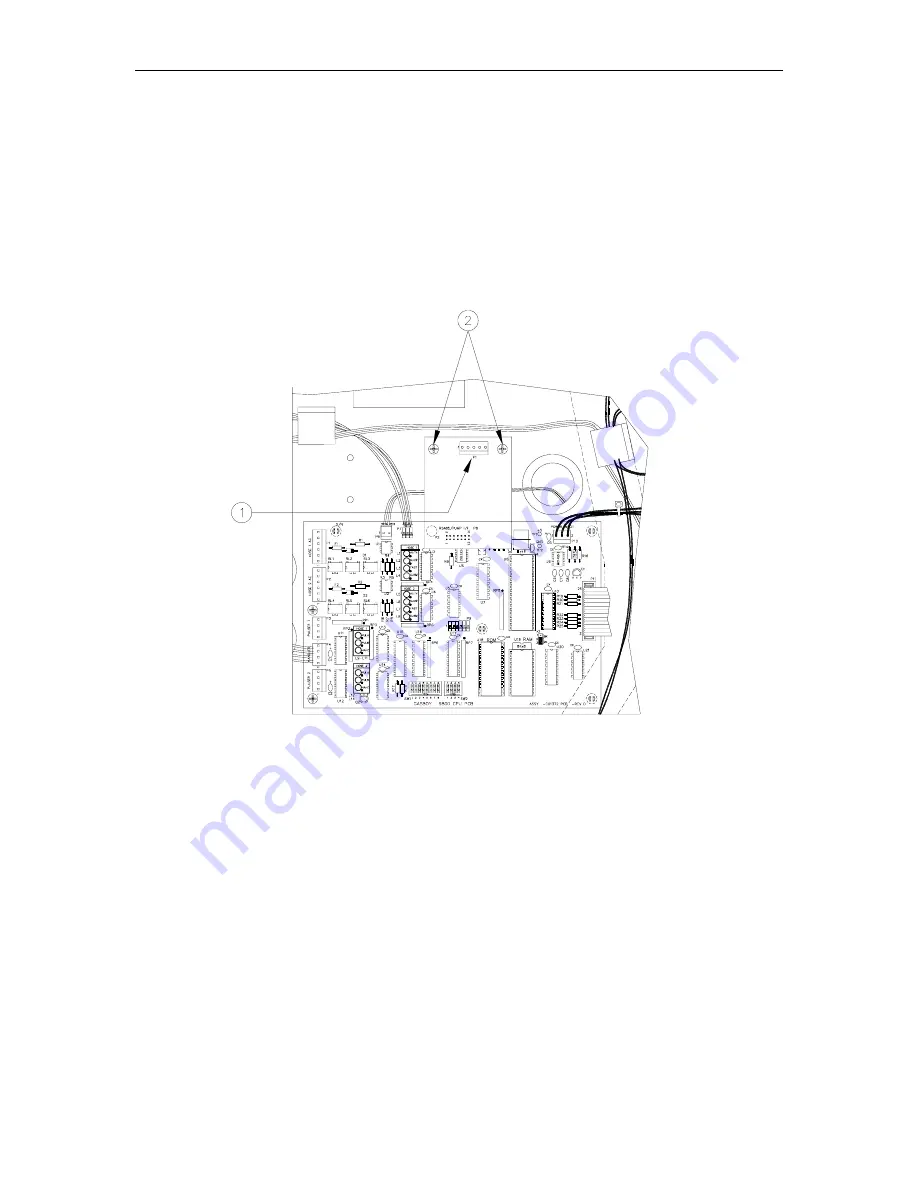
REPLACING THE RS-485 OR PUMP I/F PCB
1.
Disconnect the connector [1] from the RS-485 or Pump I/F PCB.
2.
Remove the two Phillips screws [2] from the RS-485 or Pump I/F PCB.
3.
Pull the RS-485 or Pump I/F PCB from the CPU PCB.
4.
Reverse Steps 1 through 3 to install the new RS-485 or Pump I/F PCB.
NOTE: Older units may have a 5-position cable from DC conduit. New pump and RS-485 PCBs
have a 4-position connector. When installing the new PCB, make sure that pin 1 of the cable (red
wire) matches up with pin 1 of the PCB connector.
Summary of Contents for 9800A Series
Page 8: ......
Page 11: ...Chassis Wiring 03 07 03 2 3 115VAC 60 CYCLE PUMP WIRING...
Page 12: ...GASBOY Series 9800A 2 4 03 07 03 115VAC 60 CYCLE DISPENSER WIRING...
Page 13: ...Chassis Wiring 03 07 03 2 5 230VAC 50 CYCLE PUMP WIRING...
Page 14: ...GASBOY Series 9800A 2 6 03 07 03 230VAC 50 CYCLE DISPENSER WIRING...
Page 15: ...Chassis Wiring 03 07 03 2 7 115VAC 60 CYCLE FRONT LOAD OPTION PUMP WIRING...
Page 16: ...GASBOY Series 9800A 2 8 03 07 03 115VAC 60 CYCLE FRONT LOAD OPTION DISPENSER WIRING...
Page 17: ...Chassis Wiring 03 07 03 2 9 230VAC 50 CYCLE FRONT LOAD OPTION PUMP WIRING...
Page 18: ...GASBOY Series 9800A 2 10 03 07 03 230VAC 50 CYCLE FRONT LOAD OPTION DISPENSER WIRING...
Page 19: ...Chassis Wiring 03 07 03 2 11...
Page 20: ......
Page 39: ...Electronic Head Assembly 03 07 03 3 19 Connectors Relay Drive Pump Motor Power...
Page 60: ......
Page 65: ...Replacement Instructions 03 07 03 5 5...
Page 72: ...GASBOY Series 9800A 5 12 03 07 03...
Page 75: ......
Page 76: ...APPENDIX PARTS LIST...
Page 77: ......


