Maintenance Manual
190-02472-02
G3X Touch EFIS Part 23 AML STC
Revision 2
Page B-15
B.8 Antennas
This section contains general information for interfaced GPS, GPS/WAAS, SXM, and ADS-B antennas.
This STC provides installation approval only for the Garmin glareshield-mounted GPS Antenna (011-
04036-00), refer to the
G3X Touch EFIS Part 23 AML STC Installation Manual
(190-02472-01) for
installation guidance. All other antennas are approved as interface only and require separate installation
approval.
A minimum of one GPS antenna is required for G3X installations as the connected GDU (PFD) will share
GPS data with the second GDU (if installed). Additional GPS antennas may be used for redundancy but
are not required.
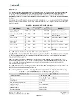
Table B-7 – Supported GPS & SXM Antennas
Make & Model
P/N
Approved G3X
Function
LRU
Connection
Mounting
Comant 2480-201
(GPS/VHF Com)
CI 2480-201
GPS
GDU 4X0
Blade antenna, external
Garmin Glareshield GPS
Antenna
011-04036-
00
GPS GDU
4X0
Glareshield mounted via hook &
loop or screws
Garmin GA 56
011-00134-
00
GPS
GDU 4X0
Stud mount, teardrop, external
Garmin GA 37
(GPS/SXM)
013-00245-
00
SXM
GDL 51R/52R ARINC 743, external
Garmin GA 55
011-01033-
00
SXM GDL
51R/52R
Stud-mount, teardrop, external
Garmin GA 55A
011-01153-
00
SXM GDL
51R/52R
Through-mount, ARINC 743,
external
The GPS antenna interface on the GDL 5XR is not used in this STC.
Only the SXM connection to the GA 37 antenna is approved in this STC. The GPS connection to the GA
37 is not compatible with any G3X LRUs but might be used for other installed equipment under their
respective interface approvals.
Also note that if a previously installed G5 is connected to a GPS antenna mounted externally on the
airframe, that antenna must be disconnected when the G5 is used as a standby instrument for G3X. It
may be possible to repurpose the external antenna for other avionics if it is compatible under their
respective interface approvals.
The GPS antenna should provide a gain of 16 to 25 dB. The GDU 4X0 supplies power to the antenna at
4.5-5.5 VDC with a maximum current of 50 mA.
The following information describes antenna performance requirements for proper system functionality.
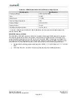
Table B-8 – GPS or GPS/WAAS Antenna Minimum Requirements
Characteristics
Specifications
Frequency Range
1565 to 1585 MHz
Gain
16 to 25 dB typical, 40 dB max.
Noise Figure
<4.00 dB
Nominal Output Impedance
50
Ω
Supply Voltage
4.5 to 5.5 VDC
Supply Current
up to 50 mA
Output Connector
BNC or TNC
Summary of Contents for G3X Touch
Page 36: ......


