background image


Maintenance Manual 

190-02472-02 

G3X Touch EFIS Part 23 AML STC 


Revision 2 

Page A-1 

APPENDIX A    INSTALLATION SPECIFIC INFORMATION 

A copy of this appendix must be used to record information for a specific installation of the G3X Touch 
EFIS Part 23 AML STC system.  The completed copy must be kept with the aircraft permanent records.  
This appendix includes the following information: 

A.1 Maintenance Records 

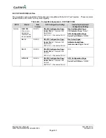
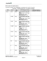
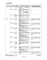
This Post-Installation Configuration Log should be completed during the initial installation, with any 
software modifications post initial installation, and maintained with the aircraft permanent records.  

  G3X software version used to perform software updates. 

  Record part and serial numbers of all LRU’s at installation. 

  Record Mod Status of all LRU’s at installation. 

  Record part and serial numbers of any LRU which was replaced. 

  Record any database updates which were performed during maintenance.   

  Any other applicable information related to the maintenance work performed on the aircraft. 

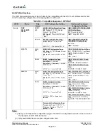
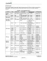
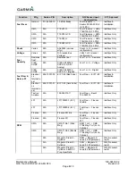
Table A-1 – G3X Post-Installation Log 

Post-Installation Configuration Log


Date: 


Aircraft Model: 


Aircraft Make: 


Aircraft 
Registration #: 


Aircraft Serial #:   

Engine: 


Original Software Version: 


New Software Version (if 
applicable): 


Unit/Option 

Installed/Enabled? 

(check if installed or 

configured) 

LRU Part Number 

LRU Serial 

Number


Mod Status 

GDU 460


GDU 470


GMU 11


GSU 25D


GTP 59


GAD 29B


GAD 27


GEA 24


GDL 5XR


Summary of Contents for G3X Touch

Page 1: ...190 02472 02 2019 Revision 2 Garmin G3X Touch Electronic Flight Instrument System Part 23 AML STC Maintenance Manual Contains Instructions for Continued Airworthiness for STC SA01899WI...

Page 2: ...rint one copy of this manual or of any revision hereto provided that such electronic or printed copy of this manual or revision must contain the complete text of this copyright notice and provided fur...

Page 3: ...foreign nationals inside or outside the United States without first obtaining an export license A violation of the EAR may be subject to a penalty of up to 10 years imprisonment and a fine of up to 1...

Page 4: ...llectual property rights in and to the Software remain with Garmin and or its third party providers You acknowledge that the Software is the property of Garmin and or its third party providers and is...

Page 5: ...ld result in serious injury damage to equipment or death NOTE All screen shots used in this document are current at the time of publication Screen shots are intended to provide visual reference only A...

Page 6: ...sual Inspection 29 4 5 Electrical Bonding Test 29 4 6 GSU 25D Earth Magnetic Field Updates 30 4 7 Special Inspection Requirements 30 5 TROUBLESHOOTING 31 5 1 General Troubleshooting 31 5 2 CAN Bus Net...

Page 7: ...4 NAV Receiver Check 94 8 5 ADS B Traffic Interface Check 95 8 6 TIS A Traffic Interface Check 95 8 7 WX 500 Stormscope Interface Check 96 8 8 FIS B Weather via ADS B In 96 8 9 GDL 51R 52R SXM Weathe...

Page 8: ...gure 3 9 Configuration Mode Pages 24 Figure 5 1 Incorrect CAN Bus Topographies 33 Figure 5 2 Correct CAN Bus Wiring Example and Node Connections 33 Figure 5 3 Network Error Rate Configuration Diagnost...

Page 9: ...5 Figure 7 1 Aircraft Level Attitude 78 Figure 7 2 Pitch Roll Offset Calibration in Progress 79 Figure 7 3 Pitch Roll Offset Completion Status 79 Figure 7 4 Compass Rose Starting Position 80 Figure 7...

Page 10: ...P271 J271 Pin Functions 52 Table 5 20 TB273 Terminal Functions 54 Table 5 21 P241 J241 Pin Functions 54 Table 5 22 P242 J242 Pin Functions 55 Table 5 23 P243 J243 Pin Functions 56 Table 5 24 P244 J244...

Page 11: ...s for continued airworthiness as defined by 14 CFR Part 23 1529 Appendix G Information in this document is required to maintain the continued airworthiness of the G3X Touch EFIS systems 1 1 1 Applicab...

Page 12: ...EFIS system Section 5 Troubleshooting Provides troubleshooting information to aid in diagnosing and resolving potential problems with equipment and functions installed by this STC Section 6 G3X Equip...

Page 13: ...w FIS B Flight Information Service Broadcast GA Go Around GAD Garmin Adapter GDL Garmin Datalink LRU GDU Garmin Display Unit GEA Garmin Engine and Airframe Unit GFC Garmin Automatic Flight Control Sys...

Page 14: ...ation Service Broadcast TIT Turbine Inlet Temperature TNC Threaded Neill Concelman TSO Technical Standard Order TX Transmit UAT Universal Access Transceiver UHF Ultra High Frequency VDC Volts of Direc...

Page 15: ...de for Certified Aircraft 190 02472 01 Garmin G3X Touch EFIS Part 23 AML STC Installation Manual 1 5 Revision and Distribution This document is required for maintaining the continued airworthiness of...

Page 16: ...FD or MFD When two GDUs are installed one as PFD and the other as an MFD failure of one display unit will cause the system to automatically revert to a reversionary format In the reversionary format p...

Page 17: ...ir data information Slip skid and rate of turn indication Synthetic Vision including Pathways and Flight Path Marker Horizontal Situation Indicator HSI Flight Director display with GFC500 autopilot mo...

Page 18: ...within the pilot s primary field of view Below is a list of some of the functions provided by the GDU 470 Many of the listed functions depend on optional equipment interfaces and or subscription serv...

Page 19: ...propriate sections in the G3X Touch EFIS Part 23 AML STC Installation Manual 190 02472 01 for interconnect and configuration information BNC connector for GPS antenna only required on PFD One GDU 470...

Page 20: ...s connected to existing primary pitot static system Only one GSU 25D is approved for installation and interface by this STC Figure 2 3 GSU 25D ADAHRS 2 1 4 GMU 11 Magnetometer The Garmin GMU 11 Magnet...

Page 21: ...D 27 provides a stabilized 12V power output to keep EIS online during engine start when battery voltage drops It is installed on airplanes with a 14 volt electrical system that install the G3X EIS opt...

Page 22: ...only provides information for the EIS sensors that were installed by the G3X Touch EFIS Part 23 AML STC Table 2 1 lists the sensors that are maintained in this manual Refer to the applicable maintenan...

Page 23: ...eive FIS B weather over the UAT link The GDL 5XR products provide information to G3X Touch displays via RS 232 and to devices running Garmin Pilot via a Connext data connection via Bluetooth Please se...

Page 24: ...anual 190 02472 02 G3X Touch EFIS Part 23 AML STC Revision 2 Page 14 Figure 2 10 GPS Antenna 2 2 G3X Optional Interfaces See APPENDIX B for equipment that may be connected to and interfaced with a G3X...

Page 25: ...nal G3X Equip Interfacing Equip KEY RS 232 Backup EIS GTS 8XX TAS TCAS Optional 5 RS 232 A429 WX 500 Storm scope Optional RS 232 GMC 507 A P Controller Optional GSA 28 Yaw Servo Optional GSA 28 Trim S...

Page 26: ...luding GSU 25D and GEA 24 When two external navigators are connected the 1 Nav must be connected to a lower numbered RS 232 port on the PFD and the 2 Nav connected to either a higher numbered port on...

Page 27: ...ection 2 1 7 for applicability 2 4 Electrical Power Distribution Electrical load information for the G3X Touch EFIS system LRUs is provided below in Table 2 4 Appendix A of this document contains deta...

Page 28: ...wer bezel is context sensitive and is identified on the screen just above the associated knob Reference Section 3 2 2 1 for using the GDU knob in configuration mode Menu Button Used to enter configura...

Page 29: ...e 3 2 Display Modes 3 2 1 Normal Display Mode PFD Two PFD display formats are available in normal mode and controlled by the split full touch field on the upper portion of the display Refer to Figure...

Page 30: ...e 20 Figure 3 2 Split Full Format Buttons GDU 460 Figure 3 3 Split Full Format Buttons GDU 470 The location of the split full button and the format to be displayed at start up are configured in the Di...

Page 31: ...S Example MFD provides a multi function area with various pages and EIS if configured The display on a 7 GDU 470 when configured as an MFD does not have split format functionality in normal mode but i...

Page 32: ...nary format in the event of a GDU failure In the reversionary mode primary flight information radio tuning information and EIS if installed are displayed on the remaining GDU 3 2 2 Configuration Mode...

Page 33: ...tion will be displayed on the screen above the knob for example Move Selector Scroll List etc may be displayed If the inner and outer knobs have the different functions that would be displayed on the...

Page 34: ...ONDITION The LRU is online and reports the item located next to the indicator box is communicating The LRU is online and reports the item located next to the indicator box is not communicating a fault...

Page 35: ...information reference section 5 2 To enter configuration diagnostic mode 1 Simultaneously hold down the MENU and NRST key on the GDU 4X0 while applying power to the aircraft until the Configuration d...

Page 36: ......
Page 37: ...er replacing or servicing electrical components near the GMU 11 magnetometer the Magnetometer Interference Test reference Section 5 and Magnetometer Calibration Procedure reference Section 7 must be p...

Page 38: ...eld Model Update 4 6 When available 5 year update cycle GMU 11 Removal Replacement 6 3 On Condition GTP 59 Removal Replacement 6 4 On Condition Special Inspection Requirements 4 6 On Condition GAD 27...

Page 39: ...ation for grounding of a GSU 25D GEA 24 GAD 29B or GAD 27 refer to Appendix A of this document must be inspected every 12 calendar months The inspection must verify that the foil tape is not torn dama...

Page 40: ...netic Reference Field update is expected to be available from Garmin in July 2020 and every five years thereafter as long as the GSU 25D remains a Garmin supported product The IGRF model is automatica...

Page 41: ...er or Garmin Aviation Product Support at US Toll Free Number 1 888 606 5482 or US 1 913 397 8200 NOTE Any warning message indicated on the Messages field or anywhere on the display while on ground sho...

Page 42: ...9B GEA 24 GSU 25D GAD 27 and GSA 28 if GFC 500 is installed have an LED on their outer cases that indicates the LRU s current status The status indications are shown in Table 5 1 Table 5 1 Status LED...

Page 43: ...described above When adding a new device to the CAN bus evaluate proposed modifications to the CAN bus wiring connections to ensure compliance with all above requirements and the G3X Touch EFIS Part 2...

Page 44: ...displayed for Network Error Rate is a steady 0 Figure 5 3 Also verify the other network counts values listed on Table 5 3 Figure 5 3 Network Error Rate Configuration Diagnostic Mode NOTE CAN issue mi...

Page 45: ...01 for further detail If the above steps do not result in acceptable display legibility the GDU may need to be replaced Contact Garmin Product Support for more information 5 3 2 SD Card Slot A stuck...

Page 46: ...GDU display Update databases as required Navigation Terrain Obstacle Database Mismatch Indicates that the GDU displays have different versions of the specified database Update the databases in all GD...

Page 47: ...s measured Outside Air Temperature OAT A valid OAT will display a number Indicated Airspeed IAS True Airspeed TAS A valid OAT value is required to calculate TAS Barometric Altitude Density Altitude Pr...

Page 48: ...72 01 AHRS not receiving magnetometer data Communication lost between GSU 25D and GMU 11 Inspect GMU 11 wiring Ensure the GMU 11 installation is in accordance with the G3X Touch EFIS Part 23 AML STC I...

Page 49: ...intermittent or a yellow degraded is displayed on the heading Figure 5 4 use guidance in Table 5 6 and check the following while the aircraft is on the ground 1 When taxiing without reliable GPS info...

Page 50: ...RS invalidating its output or a communication path failure 3 What exactly was the aircraft doing in the two minutes that preceded the failure taxing on the ground flying straight and level flight turn...

Page 51: ...it Orientation and Pitch Roll Offset Compensation are not required prior to this execution of this procedure A sequence of activities to be performed during a magnetometer interference test is shown i...

Page 52: ...der and at the precise elapsed time as specified in the prepared test sequence 6 After completing the prepared test sequence press the Done softkey Ensure that a PASSED message appears on the display...

Page 53: ...p 2 20 Autopilot On 2 30 Autopilot Off 2 40 Electric Trim GFC 500 2 50 Landing Gear Up 3 00 Landing Gear Down 3 10 Speed Brake Up 3 20 Speed Brake Down 3 30 Navigation Lights On 3 40 Navigation Lights...

Page 54: ...the GMU 11 5 5 Engine Indication Troubleshooting EIS indication failures may be presented as red x s on the gauges as shown in Figure 5 9 or as operation anomalies Reference Table 5 8 below for troub...

Page 55: ...rify wiring and connections Air contamination in the sensor Purge fuel lines of air verify sensor orientation and clean the sensor Interference Route wires away from spark plug leads and power wires I...

Page 56: ...ess characters If the flight ID was entered via GTX tool correct it 5 8 Loss of Navigation Information External Navigators If VHF GPS Navigation information is removed from the G3X Touch GDU and GPS i...

Page 57: ...is functioning properly Reference the autopilot manufacturer s troubleshooting procedures 6 If problem persists replace the GAD 29B with a known good unit 5 11 Miscellaneous Alerts Table 5 12 Miscella...

Page 58: ...4X01 The aircraft harness connector J4X01 is a 9 socket D sub plug connector and interfaces to the GDU P4X01 connector A pinout arrangement of P4X01 is shown in Figure 5 10 Connector pin functions are...

Page 59: ...ERT AUDIO OUT LO OUT 19 RESERVED 20 RESERVED 21 RESERVED 22 RESERVED 23 RS 232 RX 4 IN 24 RS 232 RX 5 IN 25 RESERVED 26 28V LIGHTING BUS HI IN 27 SYSTEM PROGRAM GROUND 28 CAN BUS TERMINATION 29 RS 232...

Page 60: ...nnector on the GSU A pinout arrangement of J251 is shown in Figure 5 12 and connector pin functions are shown in Table 5 15 Figure 5 12 View of J251 Connector on the GSU 25D Table 5 15 P251 J251 Pin F...

Page 61: ...tor This section describes the GMU 11 aircraft harness and interface connector The GMU LRU connector designation is J111 and he aircraft harness connector is designated as P111 The aircraft harness co...

Page 62: ...D 27 Aircraft Harness LRU Connectors This section describes the GAD 27 aircraft harness and the interface connectors on the GAD 27 The GAD 27 connector designation is J271 and the aircraft harness con...

Page 63: ...ESERVED 30 RESERVED 31 RESERVED 32 RESERVED 33 RESERVED 34 RESERVED 35 RESERVED 36 RESERVED 37 RESERVED 38 GAD 27 POWER GROUND 39 RESERVED 40 RESERVED 41 RESERVED 42 RESERVED 43 RESERVED 44 RESERVED 4...

Page 64: ...es the GEA 24 aircraft harness and LRU interface connectors The GEA connector designations are J241 J242 J243 and J244 and the aircraft harness connectors are designated as P241 P242 P243 and P244 res...

Page 65: ...connector pin functions are shown in Table 5 22 Figure 5 18 View of J242 Connector on the GEA 24 Table 5 22 P242 J242 Pin Functions PIN PIN NAME I O 1 RESERVED 2 CHT CYL 6 LO IN 3 EGT CYL 6 LO IN 4 CH...

Page 66: ...R 12V OUT 4 FUEL PRESS XDCR 5V OUT 5 RPM 2 GND 6 RPM 2 IN 7 RPM 1 GND 8 RPM 1 IN 9 RPM 1 12V OUT 10 RPM 2 12V OUT 11 RESERVED 12 MANIFOLD PRESS GND 13 MANIFOLD PRESS RX IN 14 MANIFOLD PRESS XDCR 12V O...

Page 67: ...tions are shown in Table 5 24 Figure 5 20 View of J244 Connector on the GEA 24 Table 5 24 P244 J244 Pin Functions PIN PIN NAME I O 1 RESERVED 2 RESERVED 3 RESERVED 4 RESERVED 5 RESERVED 6 FUEL QTY 1 I...

Page 68: ...terface connectors The GAD 29 connector designations are J291 and J292 and the aircraft harness connectors are designated as P291 and P292 respectively 5 12 7 1 Aircraft Harness Connector P291 The air...

Page 69: ...OUT 9 CAN TERM 1 10 ARINC 429 RX 2B IN 11 ARINC 429 RX 1B IN 12 ARINC 429 TX 1B OUT 13 ARINC 429 TX 1B OUT 14 HEADING ERROR LO IN 15 COURSE ERROR HI OUT 16 ARINC 429 RX 4A IN 17 ARINC 429 RX 3A IN 18...

Page 70: ...on the GDL 5XR Table 5 27 P5X1 J5X1 Pin Functions PIN PIN NAME I O 1 RESERVED 2 RESERVED 3 RESERVED 4 RESERVED 5 RS 232 TX 2 OUT 6 RS 232 RX 2 IN 7 RS 232 TX 1 OUT 8 RS 232 RX 1 IN 9 POWER GROUND 10...

Page 71: ...2472 01 appropriate hardware part numbers 6 1 GDU 4X0 Removal 1 Power OFF the aircraft to remove power from the GDU and other LRUs 2 Using a 3 32 hex tool rotate all four fasteners counter clockwise t...

Page 72: ...ins control of other LRUs configuration and calibration settings such as the GSU 25D This allows critical data to be retained with the airframe even if the PFD display is replaced NOTE All item number...

Page 73: ...nector on the back of the GDU 6 Reinstall the PFD in accordance with Section 6 1 Figure 6 2 Configuration Module PFD Table 6 1 GDU Configuration Module Kit P N 010 12253 01 Item Description Qty Requir...

Page 74: ...ach the GSU 25D to the back of the GDU Figure 6 3 GDU 460 Mounted GSU 25D GDU 470 similar Remote mounted GSU 25D 1 Gain access to the GSU 25D Refer to the location information recorded in APPENDIX A o...

Page 75: ...Place the GSU 25D on the mounting location in the same mounting orientation as it was when removed Align GSU holes with the holes on the mounting location Connect the electrical connectors to the GSU...

Page 76: ...electrical connector to the GMU 11 5 Continue to section 7 2 for configuration calibration and checkout procedures Figure 6 5 GMU 11 Magnetometer 6 4 GTP 59 Temperature Probe Removal 1 Ensure power i...

Page 77: ...lock for proper reinstallation 3 Remove the four screws and washers and nuts as applicable that secure the GAD 27 to the mounting location 4 Lift the GAD 27 off the mounting location Reinstallation 1...

Page 78: ...aft records 2 Disconnect the GEA 24 electrical connectors 3 Remove the four screws that hold the GEA to the mounting location 4 Lift the GEA 24 off its mounting location Reinstallation 1 Place the GEA...

Page 79: ...the EIS ground checkout procedure for the specific sensor that was affected in Section 8 11 6 6 1 1 Pressure Sensors Oil Manifold and Fuel Manifold pressure oil pressure and fuel pressure sensor inst...

Page 80: ...ht plus one half turn and safety wired in accordance with practices defined in Section 7 Safetying of Chapter 7 Aircraft Hardware Control Cables and Turnbuckles of advisory circular AC 43 13 1B Aircra...

Page 81: ...lope up It must not slope down more than 4 inches per foot The hoses and fittings connected to fuel flow transducer must meet the following requirements Fuel hoses must not be subject to engine or oth...

Page 82: ...tion 8 31 of AC 43 13 1B Aircraft Inspection and Repair WARNING Ensure the fuel flow transducer installation does not introduce thread sealant or debris into the fuel system CAUTION Do not blow pressu...

Page 83: ...cation information recorded in APPENDIX A of this document and maintained with the aircraft records 2 Disconnect the GDL 5XR electrical and coax cable connectors as applicable 3 Remove the four screws...

Page 84: ...on antenna to separate the fastener tape hook loop material securing the antenna on the glareshield 4 Lift up on the GPS antenna from the glareshield to remove it Reinstallation 1 Place the antenna on...

Page 85: ...Maintenance Manual 190 02472 02 G3X Touch EFIS Part 23 AML STC Revision 2 Page 75 Figure 6 14 GPS Antenna Screw mounted Installation Example Figure 6 15 GPS Antenna Hook and Loop Installation Example...

Page 86: ...o the PFD the required configuration information will be written to the new module by the PFD If both the PFD and configuration module are replaced with new modules configuration of the system is requ...

Page 87: ...ter the Magnetometer Interference Test Section 8 12 1 or Magnetometer Calibration Section 7 2 1 2 were completed requires a repeat of the Magnetometer interference test procedures If new magnetic inte...

Page 88: ...RE loosened X X X GSU 25D was replaced with new unit New serial number X X X 7 2 1 1 Pitch Roll Offset Compensation by Aircraft Leveling NOTE Prior to performing the following procedure the aircraft m...

Page 89: ...craft engine running Start and operate the aircraft engines in accordance with Pilot s Operating Handbook POH or Aircraft Flight Manual AFM 7 2 1 2 Magnetometer Calibration NOTE The Pitch Roll Offset...

Page 90: ...a heading of magnetic north 5 It is best to offset the aircraft position to the left west of the North South axis to allow turning clockwise around the site as indicated below Figure 7 4 Compass Rose...

Page 91: ...Hold current position command and instead use compass rose references to complete the heading change Dwelling at these 30 increments for the time recommended by the ADAHRS should result in successful...

Page 92: ...ll on screen instructions have been complied with and all information displayed is correct then select the Start button to begin the calibration Figure 7 9 Static Pressure Calibration Instructions 7 A...

Page 93: ...uration mode if it is not already in configuration mode 2 Select the ADAHRS Calibration Page 3 Ensure that all the required status boxes are checked 4 Select Engine Run Up Test 5 Ensure that the aircr...

Page 94: ...required 7 4 1 GTP 59 Testing 1 Verify OAT operation by observing the PFD for a valid value for OAT 2 Apply heat to the GTP 59 probe and observe OAT value rises by at least 5 Celsius 7 5 GAD 27 Origin...

Page 95: ...uired if the removed GDL 5XR is re installed Continue to Section 7 8 1 New Repaired or Exchange GDL 5XR Installed If a new repaired or exchange GDL 5XR is installed the software will be loaded to the...

Page 96: ...ouble click the exe file to download the self extracting update file onto the hard drive A window similar to the image below will pop up while extracting NOTE When the extraction begins the program au...

Page 97: ...X Touch EFIS Part 23 AML STC Revision 2 Page 87 6 A window will pop up on the screen to indicating file progress 7 Once successfully completed a message window similar to below will pop up Click Finis...

Page 98: ...or use NOTE Perform software updates on the ground only and remain on the ground while a software update is in progress 7 9 2 1 GDU Software Loading Procedure 1 Connect external power to the aircraft...

Page 99: ...wing a GDU software update This process may take up to ten minutes for all LRUs connected to the high speed CAN bus The GDL 5XR is connected via RS 232 and may take up to 30 minutes to update software...

Page 100: ...access the datalink page on the GDU press MENU key twice for the main menu then select Data Link 3 Position the aircraft in an area with an unobstructed view of the southern sky It is highly recommend...

Page 101: ...LRU status and software check The System Information page in the configuration mode of the GDU 4X0 PFD has a Devices Online tab that reports the status of installed LRU s and their currently installed...

Page 102: ...the main menu 2 On the Main menu select Setup to access setup page 3 On the Setup page select XPDR to access the transponder page 4 On the transponder page select Enabled under Ground Maintenance Tes...

Page 103: ...onitor GPS status on the Main Page Possible GPS status indications include No Antenna Autolocate Lost GPS Fix 2D GPS Fix 3D GPS Fix Searching the Sky Acquiring No GPS Fix 2D Differential 3D Differenti...

Page 104: ...vate a flight plan on the GPS navigation source 8 Verify that the active waypoint displayed in the PFD WPT field of the GDU 4X0 is the same as the active waypoint displayed on the navigator 9 On the G...

Page 105: ...r TCAS ensure there is no interference with ADS B data reception 8 5 1 TCAS Traffic Interface Check 1 Verify the GDU is in normal mode 2 Select the Traffic page on the home screen of the MFD or the mu...

Page 106: ...nd station If this is not the case it is recommended that these checks be performed in flight within range of an FAA ground station 1 Verify the G3X Touch EFIS is in normal mode 2 Verify the GPS and F...

Page 107: ...that music plays on multiple channels 8 11 EIS Check This section contains procedures to verify proper installation operation and gauge markings of the EIS Complete the following applicable checkouts...

Page 108: ...d fittings are free of leaks 8 12 ADAHRS and Magnetometer Ground Checks This section contains the ground checks that may be performed on the magnetometer for ADAHRS aspects of the G3X system 8 12 1 Al...

Page 109: ...PFD and standby ASI airspeed values are within the tolerances indicated in Table 8 2 NOTE The aircraft or instrument manufacturer s data should be referenced for standby tolerances if available Table...

Page 110: ...ble 8 3 Heading Verification ADAHRS Check Heading A Displayed ADAHRS Heading B Heading Error A B Standby Compass Heading 360 North 30 60 90 East 120 150 180 South 210 240 270 West 300 330 8 13 Garmin...

Page 111: ...or stick moves to the right 7 Adjust the heading bug to the left 8 Verify that the control yoke or stick moves to the left 9 Adjust the heading bug to the aircraft heading 10 Disengage the autopilot...

Page 112: ...with the aircraft positioned where it can receive GPS signal 1 On the GPS navigator enter a simple Direct To flight plan with a waypoint that is on the current aircraft heading and select the PFD CDI...

Page 113: ...he same rate and values match on both the G5 ADI and G3X PFD Verify the Baro field on the G5 changes to a cyan color and the digits change to black color but revert to black field with cyan digits onc...

Page 114: ...nterfere with the station ID f For each GPS Navigator enter a simple flight plan and display as appropriate i e Navigator Display PFD CDI etc if installed g Verify there are no guidance errors 9 If an...

Page 115: ...ion Lt Landing Lights Gov RPM Incr Decr Hydraulic System Radar Altimeter TAS TCAS Transponder Audio Panel Autopilot SAS add equipment here add equipment here SOURCE GDU 1 GDU 2 If installed GMU 11 Mag...

Page 116: ...ermanent records G3X software version used to perform software updates Record part and serial numbers of all LRU s at installation Record Mod Status of all LRU s at installation Record part and serial...

Page 117: ...quipment Locations Date Aircraft Make Model Aircraft Reg Serial LRU Station C G Description of Location GDU 460 in GDU 470 in GMU 11 in GSU 25D in GTP 59 in GAD 29B in GAD 27 in GEA 24 in GDL 5XR in A...

Page 118: ...Maintenance Manual 190 02472 02 G3X Touch EFIS Part 23 AML STC Revision 2 Page A 3 Figure A 1 Generic Aircraft Figure...

Page 119: ...GNS configure 1 GNS as above and 2 GNS as below 429 Output 2 EFIS Airdata Format 1 and Nav 2 429 Input 3 Garmin GPS and Nav 2 for GNS 2 If Applicable 429 Input 4 Garmin VOR ILS and Nav 2 for GNS 2 GNS...

Page 120: ...t Installed Miscellaneous Setup Page CDI Select USE GTN 6XX 7XX Software v6 51 is required ARINC 429 ARINC 429 Configuration Page 429 Output 1 EFIS Airdata Format 1 and Nav 1 429 Input 1 Garmin GPS an...

Page 121: ...on the MFD CHNL x Input Output Connext Format 2 When Connext is used 1 GTN Only NOTE x Connected Port Main Indicator Analog Config Page Selected Course for VLOC Ignored VOR LOC GS Config Page Nav Rad...

Page 122: ...AT 1 Low Speed SDI LNAV 1 RS 232 RS 232 Configuration Page Serial Port x MAPMX Serial Port x Connext CONNEXT 57600 BAUD NOTE x Connected Port GPS 175 RS 232 CHNL 1 Config Page IN OUT MAPMX FORMAT 1 GP...

Page 123: ...navigation receivers can be connected RS 232 RS 232 Configuration Page Serial Port x Garmin VHF Nav Comm NOTE x Connected Port Nav Configuration Page CDI Indicator Type Serial SYS Configuration Page...

Page 124: ...ected to Garmin Navigator Input ADS B GTN GNS RS 232 Configuration Page RS 232 CH Connected to GTX Output ADS B Format 1 GTX 345 RS 232 Transponder Configuration Page Transponder Type GTX 345 1 On scr...

Page 125: ...ffic Data Disable If direct audio connection from GTS to Audio Panel is wired perform the following Sound Configuration Page Traffic Audio Disable Traffic N A Alert Disable GTS 8XX Traffic Display Des...

Page 126: ...ot Configuration Page Autopilot Type Century 1C388C GPS Steering Enabled GPSS Scale Factor 1 000 1C388MC analog Analog Autopilot Configuration Page Autopilot Type Century 1C388MC GPS Steering Enabled...

Page 127: ...IFCS 800B IFCS analog Analog Autopilot Configuration Page Autopilot Type Cessna 300 DC Cessna 400 DC or Cessna 800 DC as applicable GPS Steering Enabled GPSS Scale Factor 1 000 Honeywell Bendix King...

Page 128: ...e Analog Autopilot Configuration Page Autopilot Type S Tec System 40 GPS Steering Enabled GPSS Scale Factor 1 000 Must be configured to operate with KI 525 KCS 55 heading system System 50 analog discr...

Page 129: ...alog Analog Autopilot Configuration Page Autopilot Type Piper AutoControl GPS Steering Enabled GPSS Scale Factor 1 000 Altimatic III IIIB 1 IIIC analog Analog Autopilot Configuration Page Autopilot Ty...

Page 130: ...0 4 Interface Installation Textron Aviation N A Beech 102 389017 1 Oil Pressure Beech 102 389017 Interface Only Textron Aviation N A Beech 102 389017 3 Oil Pressure Beech 102 389017 Interface Only UMA...

Page 131: ...S CORP N A CiES CC284022 XXXX 101 Digital Fuel 1 or 2 Digital Interface Only Fuel Flow Return FF Electroni cs Internatio nal 494 10001 00 EI FT 60 Red Cube Fuel Flow EI FT 60 Interface Installation El...

Page 132: ...6 Cylinder 0 64200 1 Prop Gear Ratio RPM Magneto P Lead 2 337 pulse rev N A No sensor req d N A Magneto P lead 6 Cylinder 0 66700 1 Prop Gear Ratio RPM Magneto P Lead 2 249 pulse rev N A No sensor req...

Page 133: ...ernal Garmin GA 55 011 01033 00 SXM GDL 51R 52R Stud mount teardrop external Garmin GA 55A 011 01153 00 SXM GDL 51R 52R Through mount ARINC 743 external The GPS antenna interface on the GDL 5XR is not...

Page 134: ...B 9 ADS B Antenna Interface The GDL 50R or GDL 52R requires an external monopole or blade type ADS B antenna for reception The antenna should be mounted on the bottom of the aircraft and located at le...

Reviews: