Maintenance Manual
190-02472-02
G3X Touch EFIS Part 23 AML STC
Revision 2
Page 99
6. On the pitot static test set, change the airspeed until the PFD airspeed tape pointer is at the
bottom of the green band (Vs1).
7. Verify that the bottom of the green arc/band on the standby ASI and PFD airspeed tape are at the
same airspeed value.
8. Change the airspeed until the PFD airspeed tape pointer is at the top of the white band (Vfe).
9. Verify that the top of the white arc/band on the standby ASI and PFD airspeed tape are at the
same airspeed value.
10. Change the airspeed until the PFD airspeed tape pointer is at the top of the green band/bottom of
the yellow band (Vno).
11. Verify that the top of the green arc/band on the standby ASI and PFD airspeed tape are at the
same airspeed value.
12. Increase the airspeed to the upper red radial/top of yellow arc (Vne).
13. Verify that the red radial on the standby ASI and PFD airspeed tape are at the same airspeed
value.
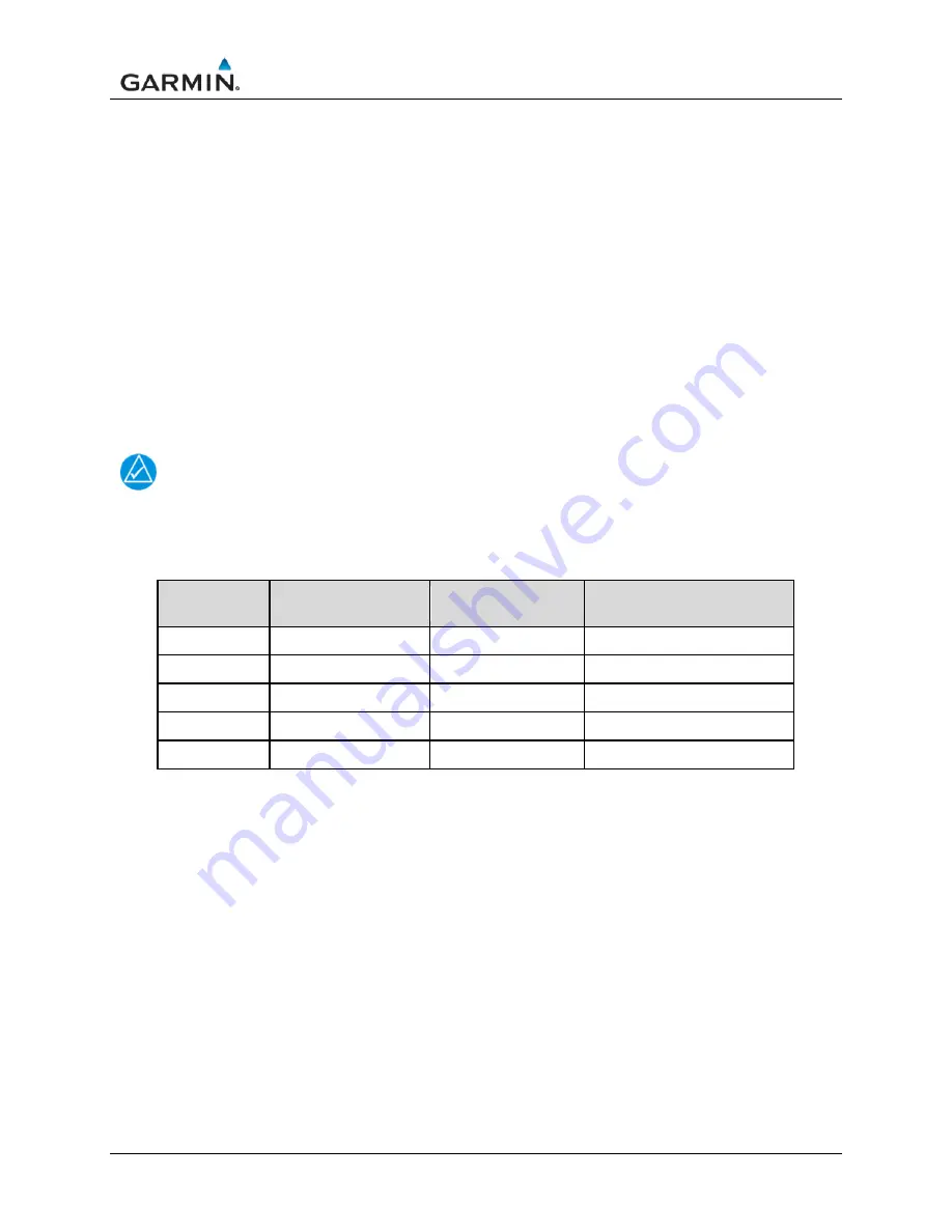
14. Starting at the current airspeed, decrease the airspeed to zero, stopping at each of the airspeeds
listed in Table 8-2. verifying that the PFD and standby ASI airspeed values are within the
tolerances indicated in Table 8-2.
NOTE
The aircraft or instrument manufacturer’s data should be referenced for standby tolerances, if
available.
Table 8-2 – Airspeed Test Points
Test Set
(KTS)
Allowed Tolerance
(+/- KTS)
Recorded Result
GDU
Recorded Result G5 (or
installed Standby ASI)
50 5.0
80 3.5
100 2.0
120 2.0
150 2.0
8.12.3 Compass Swing
After the Magnetometer Calibration Procedure is completed, a compass swing must be performed to
verify the ADAHRS/GMU 11 heading accuracy.
1. Verify ‘Auto Mag. Variation’ is selected.
o
With the PFD in Normal mode, navigate to the Position Setup Page (Menu
→
Main Menu
→
Setup
→
Position).
o
Under Heading tab, ensure ‘Auto Mag. Variation’ is selected.
o
Return to the main screen.
2. With the PFD in normal mode, all of the aircraft and avionics systems powered and operating
normally, position the aircraft on a known compass rose at a heading 360° (North), or select a
level and magnetically clean location and use a sight compass to position the aircraft to a heading
of 360° (North)
3. Record the HDG value displayed on the PFD as indicated in Table 8-3, below. Also record the
heading displayed on the standby compass. Verify or correct the standby compass deviation
card.
4. Repeat step 2 for each of the headings listed in Table 8-3.
Summary of Contents for G3X Touch
Page 36: ......

