Maintenance Manual
190-02472-02
G3X Touch EFIS Part 23 AML STC
Revision 2
Page 95
8.5 ADS-B Traffic Interface Check
NOTE
The following steps may be performed as a ground check as long as the aircraft is within range
of an FAA ground station with available targets of opportunity. If this is not the case, it is
recommended that these checks be performed in flight within range of an FAA ground station.
If the installed system is configured to receive ADS-B In data through an interface with an ADS-B In
capable unit (GNX 375, GTX 3X5 or GDL 50R/52R), the interface is verified as follows:
1. Verify the GDU is in normal mode.
2. Select the Traffic page on the home screen of the MFD or the multi-function pane on the PFD.
3. Turn on the interfacing ADS-B In capable equipment.
a. If the installation includes TAS/TCAS correlated traffic, turn on the TAS/TCAS source.
4. Make sure an amber NO DATA or TRAFFIC FAIL messages are not displayed over or below the
“ownship” icon.
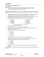
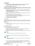
5. Make sure there are no FAIL annunciations in the upper left-hand corner of the traffic status
window. Depending on installation either
or
should be displayed if ADS-B
Interface is correct.
a. If the installation includes TAS/TCAS correlated traffic, verify that the TAS/TCAS status is
either OPER or STBY.
6. Observe targets of opportunity from ADS-B equipped aircraft, or an FAA ground station.
7. Apply power to any installed L-band equipment such as transponders, DME or TCAS, ensure
there is no interference with ADS-B data reception.
8.5.1 TCAS Traffic Interface Check
1. Verify the GDU is in normal mode.
2. Select the Traffic page on the home screen of the MFD or the multi-function pane on the PFD.
3. Verify that no TAS/TCAS failure annunciations (“NO DATA”, “TRFC FAIL”, “NO TRFC DATA”,
“DATA FAILED”, “FAILED”) are shown on the traffic map.
4. In the upper left corner of the Traffic Map page, verify that the Traffic Status is either TAS/TCAS:
OPER or TAS/TCAS: STBY (“TIS: FAIL” or “TAS/TCAS: FAIL” must not be displayed).
5. Select the Traffic Status button and change the mode between Operate and Standby.
6. Verify that the mode of the traffic system is updated accordingly.
7. Put the traffic system in Standby mode.
8. Initiate a traffic system self-test by selecting the Test button at the bottom of the page. Note: The
Self-Test button will not be selectable if the traffic system is not powered on or is in a failed
status.
9. Verify that the traffic system runs a self-test and the self-test traffic pattern is displayed.
8.6 TIS-A Traffic Interface Check
If a Garmin GTX 3X5 transponder is connected to the G3X Touch system and no other traffic systems
covered in this manual is installed, the traffic interface is verified as follows:
1. Verify the PFD is in normal mode. For a dual GDU installation verify both are in normal mode,
and test is performed on the MFD.
2. For single GDU installations, select the Traffic page in split screen format on PFD.
3. Turn on the GTX 3X5 by pressing ALT on the GTX.
4. Verify that the Traffic Status is not TIS Fail.
5. Verify that the amber NO DATA is not displayed over the “ownship” symbol.
Summary of Contents for G3X Touch
Page 36: ......

