


13-18-607 Page 56
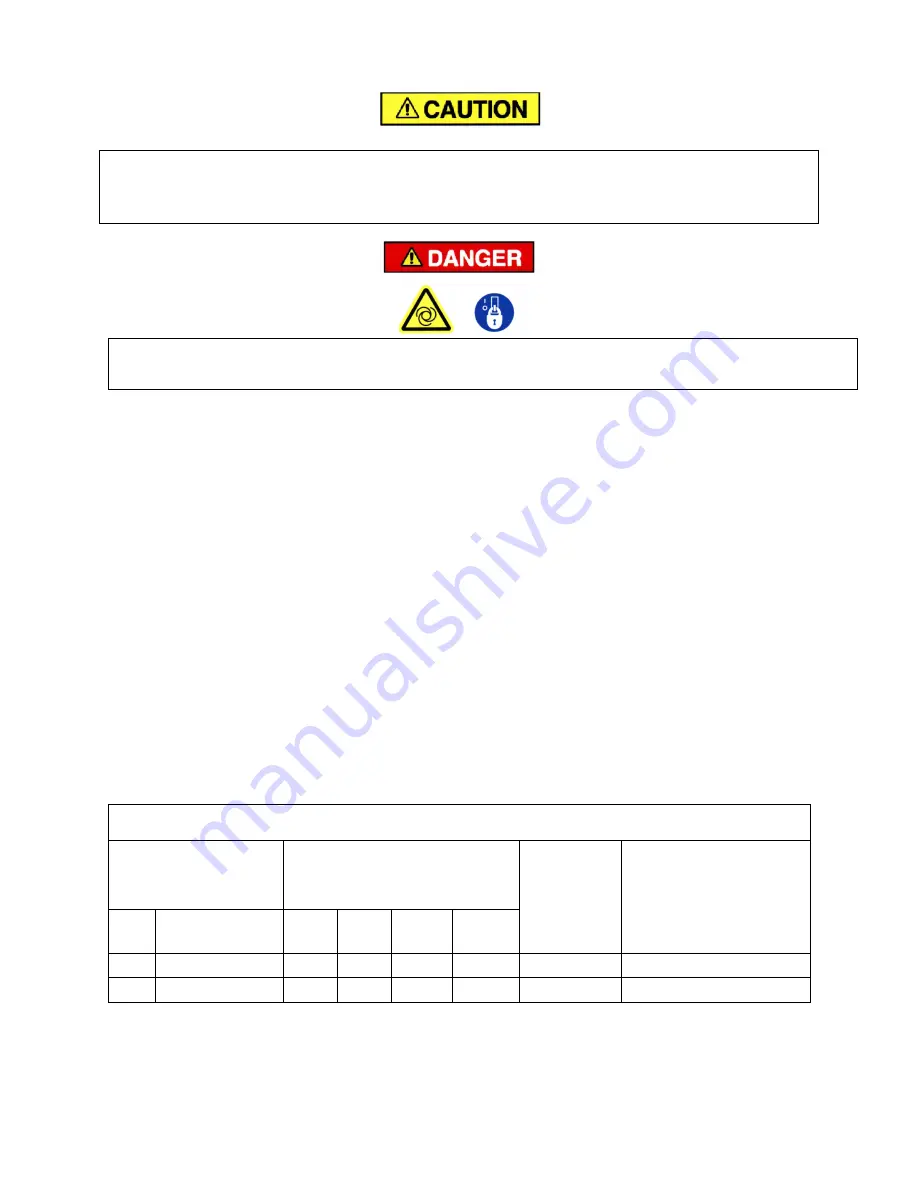
The ventilation system for the air-cooled package relies on positive back pressure to cool the heat
exchanger. Make sure that the enclosure panels that surround the heat exchanger area are closed
during compressor operation, or the compressor discharge temperature will reach shutdown
levels quickly.
Automatic restarting or electrical shock can cause injury or death. Disconnect,
lockout and tagout package from the power supply.
AXIAL COOLING FANS
1. Follow the Lock-Out Tag-Out procedures to de-energize the package. Allow adequate time for the
VFD capacitors to fully discharge before beginning maintenance.
2. Exercise caution around compressor parts after stopping the package for service. Fans and coolers
will be hot after stopping the compressor.
3. Remove access panels and guards as needed to gain access to the fan blades.
4. Cover motors, mixing valves, fan motors and other electrical components to prevent damage from the
cleaning process.
5. Use a mild detergent or degreaser to soften and dissolve accumulated grime.
6. Using a soft cloth or sponge, remove the surface grime from both sides of the blade surface.
7. Wipe up and remove all traces of cleaning residue and cleaning materials.
8. Reinstall all access panels and guards that were removed to access the fans.
9. Follow the Lock-Out Tag-Out procedures to re-energize the package.
10. Jog fans to verify there is no interference with the guard or cowling ring before the package is placed
back in service.
All axial cooling fans should be inspected and cleaned at the same interval as the heat exchangers are.
Ambient conditions will determine the actual maintenance interval at each installation
WATER-COOLED HEAT EXCHANGERS
– Optional water-cooled cores (brazed-plate type) are
available. Both cores are of a counter-current and cross-flow design. The cooling water is fed to the
cores in a series arrangement
– it passes through the air core first and proceeds through the oil core
before exiting the package. Please refer to Figure 6-3 for estimates of requirements.
AIR & OIL COOLER (Series Water Piping)
Water flow requirements at
various inlet water temperatures
(gpm)
Maximum
Water Flow
(gpm) *
Approximate (total) water
pressure drop @ 90
°
F
water flow
(psi)
KW
Model
60
°
F 70
°
F
80
°
F
90
°
F
135
VS135A
25
32
48
48
48
24
170
VS170A
32
43
64
64
64
27
* Flows exceeding "Maximum Water Flow" will cause severe erosion and will void unit warranty.
Figure 6 2 – WATER-COOLED HEAT EXCHANGER COOLANT REQUIREMENTS
Summary of Contents for AirSmart VS135A
Page 29: ...13 18 607 Page 28 Figure 4 2 PIPING AND INSTRUMENTATION ILLUSTRATION 305CGF797 A Ref Drawing...
Page 31: ...13 18 607 Page 30 300CGF546 D Ref Drawing Page 2 of 4...
Page 32: ...13 18 607 Page 31 300CGF546 D Ref Drawing Page 3 of 4...
Page 33: ...13 18 607 Page 32 300CGF546 D Ref Drawing Page 4 of 4...
Page 35: ...13 18 607 Page 34 302CGF546 E Ref Drawing Page 2 of 4...
Page 36: ...13 18 607 Page 35 302CGF546 E Ref Drawing Page 3 of 4...
Page 37: ...13 18 607 Page 36 302CGF546 E Ref Drawing Page 4 of 4...
Page 39: ...13 18 607 Page 38 303CGF546 C Ref Drawing Page 2 of 4...
Page 40: ...13 18 607 Page 39 303CGF546 C Ref Drawing Page 3 of 4...
Page 41: ...13 18 607 Page 40 303CGF546 C Ref Drawing Page 4 of 4...
Page 43: ...13 18 607 Page 42 305CGF546 C Ref Drawing Page 2 of 4...
Page 44: ...13 18 607 Page 43 305CGF546 C Ref Drawing Page 3 of 4...
Page 45: ...13 18 607 Page 44 305CGF546 C Ref Drawing Page 4 of 4...
Page 81: ......