


7
For low and high temperature alarm, assign alarm to
number of Temperature Indicator LEDs illuminated:
3 = low, 20 = high
(4) Day of week (1 = Sunday, 7 = Saturday)
(5) Time (24 hour format, hour, minutes)
(6) Hours to service (0-9999)
(7) Operating mode, M=X (S = schedule running,
M = manual override)
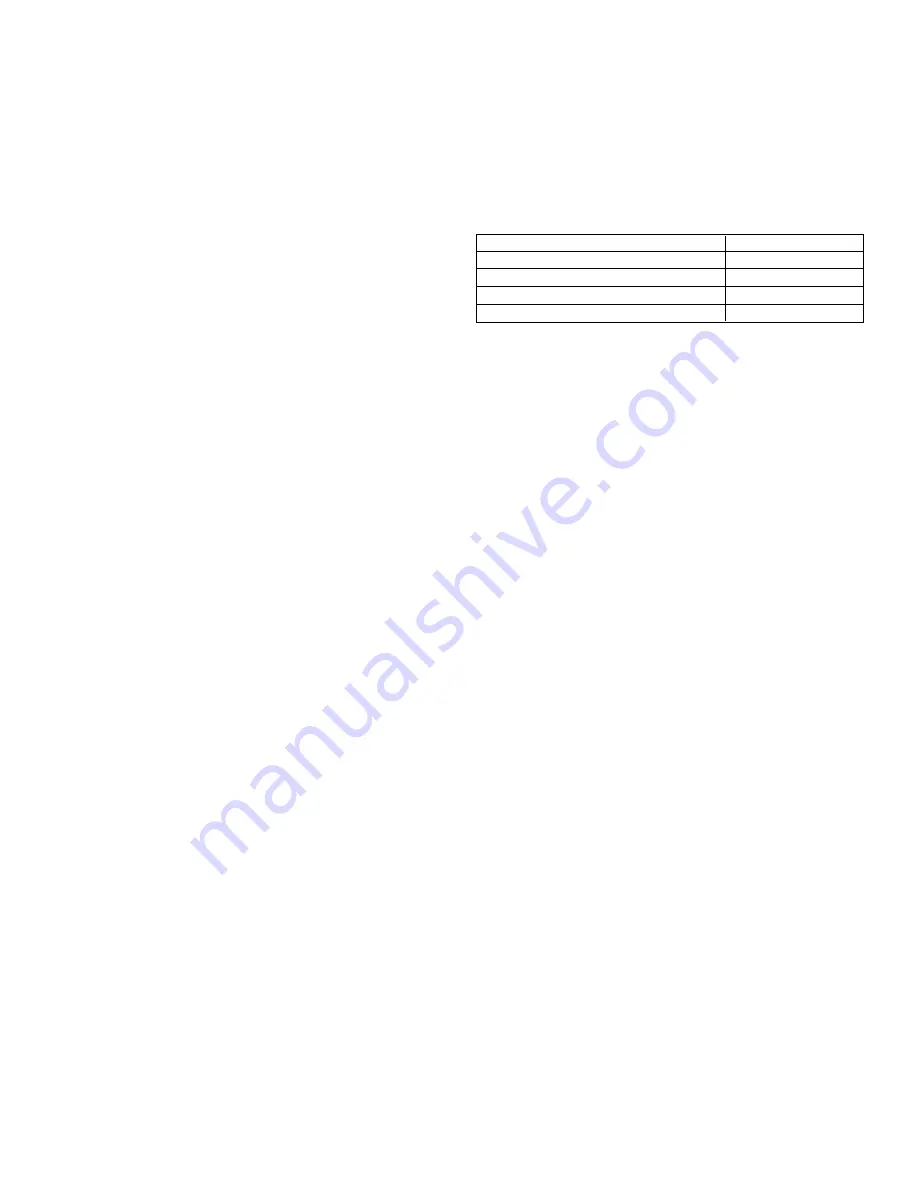
For remote start/stop operation - while powered up,
operator is allowed to change to any of the following by
sending the ASCII code below:
Operating State
ASCII Code
schedule mode, compressor off
“CTRL-Q”
schedule mode, compressor on
“CTRL-R”
manual mode, compressor off
“CTRL-S”
manual mode, compressor on
“CTRL-T”
F.
Using the factory wired auxiliary contact (option)
If ordered with this option the monitor is equipped with
an auxiliary set of dry (volt-free) contacts (one set of
normally open contacts, and one set of normally closed
contacts) which can be used to operate an auxiliary
device (e.g., an air line solenoid valve). Rating 5 amps @
24VDC or 240VAC
1.
These contacts can be activated in one of the following
modes: (depending on options ordered)
a.
Schedule Driven Mode - the contacts will be
energized and de-energized according to the
schedule inputted by the operator of the dryer. If
the refrigeration compressor shuts down on a fault
condition, the contacts will remain energized (or de-
energized) according to the schedule. The contacts
will operate independently of the refrigeration
compressor in both the manual override and
schedule running modes.
NOTE: The mode is factory set based on the option ordered.
b.
Dryer Driven Mode- the contacts will be energized
and de-energized in parallel with the refrigeration
compressor of the dryer. Therefore, if the
refrigeration compressor is on, the contacts are
energized; if the refrigeration compressor is off
(manually or by a system fault condition), the
contacts will be de-energized.
NOTE: It is the responsibility of the end-user to properly
design the system control circuitry when using the auxiliary
contact feature.
c.
To change the factory set Schedule Driven or Dryer
Driven modes:
1.
De-energize unit and disconnect the power
supply to the dryer.
2.
Remove the cabinet panels as necessary to
provide access to the Monitor panel.
3.
On the rear of the circuit board, locate the
jumper pins labeled JA and JB.
4.
Move the jumper to the appropriate setting:
Schedule Driven: jumper position JA
Dryer Driven: jumper position JB
5.
Wire the auxiliary device into the terminals
1 (Normally Open), 2 (Common) and/or 3
(Normally Closed) on the terminal block TB2.
See wiring diagram for details.
6.
Reinstall the cabinet panels.
7.
Energize the unit.
HIGH TEMPERATURE - compressed air
temperature is above the set point.
NOTE: If temperature probe is shorted, Temperature indicator
will be completely illuminated.
DRAIN - electric drain contains a high water level
alarm that activates if drain fails to discharge.
f.
Check drain operation - push
Drain
(push-to-test)
button to energize electric drain. A flow of
condensate and/or air should be present at the
drain outlet.
E.
Using the RS-232 port
The RS-232 port is used to monitor dryer operation and
provide remote start/stop capability from a host com-
puter. A (1 to 1) DB-9 cable is required to connect dryer
and computer. For PC connections, data is transmitted
on pin 2, received on pin 3, ground is pin 5, pins 7 and 8
are jumpered at dryer.
Operation is at fixed baud rate of 2,400; asynchronous
format is 8 bit, no parity, 1 stop bit (“8,N,1”). No check
sum or error correction values are provided. If required,
request status string two (or more) times and compare
for agreement.
Request data by sending ASCII ? character (3FH). Re-
sponse may take up to two seconds as certain processing
functions may require completion before serial port is
acknowledged.
Dryer responds with line feed (0AH), carriage return (0DH),
and character string:
(1) (2) (3) (4) (5) (6) (7)
XXX, X, XXX, X, XXXX, XXXX, X
(1) Number of Temperature Indicator LEDs
illuminated (1-20)
(2) Compressor state, C=X (1or 031H = ON, 0 or
030H= OFF)
(3) Sum of alarm weights, A=XXX (0 - 255; e.g. high
pressure and service alarms = 132 [4 + 128])
Bit
Weight Alarm
2
4
High press. alarm (1 = alarm)
3
8
Low press. alarm (1 = alarm)
5
32
Drain alarm (1 = alarm)
7
128
Service (service required) alarm
(1 = alarm)
Summary of Contents for 9VXRD Series
Page 11: ...11...


