background image

69

69

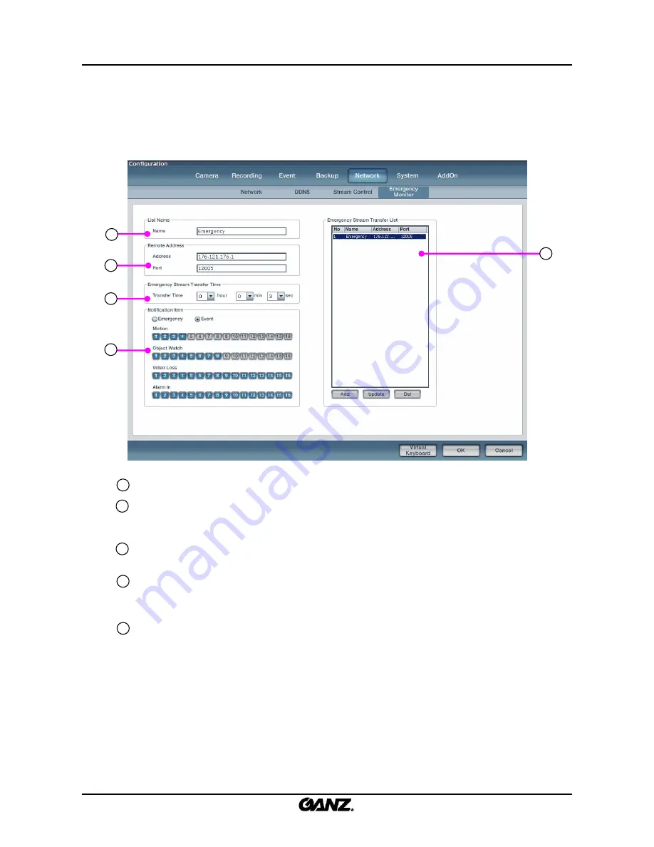
3.5.4 Emergency Monitor 

3.5.4 Emergency Monitor 

Emergency Monitor Name

: Enter the Emergency Monitor setup name for the account.

Emergency Monitor Address

: Enter the address information of the Emergency Monitor. 

Address

: Enter the IP address of the remote client computer.

Port 

: Enter the port number for transfer to the remote client compute.

Emergency Monitor Dwell Time

: Set up the dwell time of the picture and the event information on 

remote client computer when the emergency or event occurs.

Notification Item

: Select the Emergency Monitor transfer method. Emergency Monitor has two types of 

methods: ‘Emergency’ and ‘Event’. Select a channel to inform the Emergency Monitor for the options 
motion, Object Watch, Video Loss, Alarm-In.

Emergency Monitor List

: Emergency Monitor accounts can be added, deleted and edited.

Add 

: Add account in Emergency Monitor list. 

Update

: Update existing account in the Emergency Monitor list.

Delete

: Delete account in Emergency Monitor list.

1

2

3

4

5

This function transfers the pictures and data to Emergency Monitor on the client computer 
when an emergency or event occurs. You have to set up the remote IP address, port 
number and picture transfer time.

1

2

3

4

5

Summary of Contents for ZR-DHC830NP

Page 1: ...ZR DHC830NP ZR DHC1630NP ...

Page 2: ...ceivers control devices peripheral devices and the system setup instructions It is important to note here that some features figures pictures and references can only be applied to just one model ZR DHC1630NP ZR DHC830NP CBC cannot be held responsible if the DVR is damaged due to the use of non compatible devices with this product If you have any doubts please check CBC cannot be held responsible i...

Page 3: ... prohibited to post distribute or translate this manual without permission from CBC CBC is not held responsible if the DVR is damaged as a result of improper handling by a user unaware of how to operate this product or who did not consult this manual before attempting to operate the product CBC reserves the right to change the contents of this manual without notice CBC reserves all copyrights of r...

Page 4: ...urned off before installation Ensure that enough space is left for cable connections Place the system on a solid surface with sufficient air ventilation Avoid any surface that vibrates Placing the system near electronic devices such as radio or TV may cause the product to malfunction Do not disassemble the product without seeking assistance from the supplier Do not place any heavy object on the sy...

Page 5: ...t place any liquid container on the system such as water coffee or any other beverage If liquid is poured onto the system it can cause a system malfunction or fire Prevent the power cable from being severely bent or pressed by a heavy object This may cause fire Clean the dust around the system on a regular basis When cleaning the system always use dry cloth Do not use wet cloth or other organic so...

Page 6: ... system and the wall for the cables connected into the system Otherwise the cables may be bent damaged or cut This may cause fire electric shock or injuries The power outlet must be placed on a ground and the voltage range must be within 10 of the voltage rate Do not use the same outlet with a hair dryer iron refrigerator or any heating appliances This may cause fire heating and electric shock War...

Page 7: ...rom entering into the system This may cause system malfunction Do not place any heavy objects on the system This may cause system malfunction Install the system in a place with sufficient air ventilation Keep at least 15cm distance between the back of the system and the wall and at least 5cm distance between the side of the system and any walls Install the system on a stable and level surface The ...

Page 8: ...the air inside the system operation room and tighten the system cover firmly System malfunction may be caused by inappropriate environment In order to maintain stable system performance have your system checked regularly by the service center CBC is not held responsible for system breakdown caused by user mishandling It is recommended to use AVR automatic voltage regulator for stable power supply ...

Page 9: ...onnection 18 1 7 Network connection 19 2 1 Live screen 20 2 2 Login menu 22 2 3 Picture composition 23 2 4 System status 24 2 5 DB drive allocation 26 2 6 Event indication 29 2 7 Full screen display 30 2 8 Display settings 31 2 9 1 Ch playback 32 2 10 Instant backup 33 2 11 Camera picture allocation 34 2 1 2 P a n t i l t m o d e 36 2 13 System shutdown 39 2 14 Virtual keyboard 40 2 Live ...

Page 10: ... 3 1 3 A l a r m 4 9 3 1 4 E x t e r n a l m o n i t o r 5 0 3 2 R e c o r d i n g 51 3 2 1 R e c o r d i n g 5 1 3 2 2 S c h e d u l e 5 2 3 2 3 S t o r a g e C a l c u l a t o r 5 6 3 3 E v e n t 5 7 3 3 1 M o t i o n d e t e c t i o n 57 3 3 2 E m e r g e n c y 6 0 3 3 3 V i d e o l o s s 6 1 3 3 4 E m a i l 6 2 3 4 B a c k u p 6 4 3 5 N e t w o r k 6 6 3 5 1 N e t wo r k 6 6 3 5 2 D D N S 6 7 ...

Page 11: ... 2 S e q u e n c e s e a r c h 1 1 1 5 3 T h u m b n a i l s e a r c h 1 1 2 5 4 O b j e c t s e a r c h 1 1 3 5 5 P O S s e a r c h 1 1 4 Appendix 1 WebDVR 115 2 Recovery Disk instruction guide 118 3 How to do System Recovery on HDD 120 4 Specifications 122 ...

Page 12: ...the number of channels and the types of exterior equipment The system front and rear panels are subject to change without notice for quality improvements Please keep cleaning the fan filter of front panel Door Closed Door Open Power Switch USB Port CD DVD RW 1 Installation 1 1 System front panel 1 1 System front panel ...

Page 13: ... 16 Port RS485 Port Alarm Output 4 Port Audio Input Port Mouse Input Port PS 2 Keyboard Input Port PS 2 Printer Port LPT1 Serial Port COM1 USB Port Ver 2 0 Ethernet Port 100 Mbps Audio Output Port VGA Port External Monitor Output supported 16 split screen 1 2 3 4 5 6 7 8 9 10 11 12 13 14 15 1 4 2 3 5 6 7 8 9 10 11 12 13 14 15 16 16 ZR DHC1630NP ZR DHC1630NP ...

Page 14: ...larm Output 4 Port Audio Input Port Mouse Input Port PS 2 Keyboard Input Port PS 2 Printer Port LPT1 Serial Port COM1 USB Port Ver 2 0 Ethernet Port 100 Mbps Audio Output Port VGA Port External Monitor Output supported 16 split screen 1 2 3 4 5 6 7 8 9 10 11 12 13 14 15 1 4 2 3 5 6 7 8 9 10 11 12 13 14 15 16 16 ZR DHC830NP ZR DHC830NP ...

Page 15: ...o the VGA input on the VGA card Connect the camera signal to the BNC terminals coaxial type Connect the Printer to the LPT1 terminal Warning The power cable should be plugged in after all devices are connected The system will automatically boot once the power cable is plugged in The front on off switch is used when you reboot the system manually 6 The devices and cables should be connected to the ...

Page 16: ...en activated The mechanical switch can connect with either a GND or an alarm input Each alarm input terminal can be set up as NC Normal Close or NO Normal Open in the system configuration Sensor connection method 1 Connect the signal line of the sensor device with the alarm input terminal number 2 Connect the other signal line with the GND Input alarm in no 1 GND GND Input alarm in no 9 ...

Page 17: ... can be setup as NC Normal Close or NO Normal Open in the system configuration Note Connect any alarm device to the alarm out When an event occurs in the alarm in the connected alarm output will initiate the alarm device by a mechanical reply completing the circuit Control connection method 1 Connect the Signal line of the alarm device with the alarm output terminal number 2 Connect another signal...

Page 18: ...85 terminal is provided in the DVR system can be used to control the PTZ camera speed dome and other external devices For the PTZ camera connect RX and TX with the RS485 port connect RX and TX with the RS485 port Warning Make sure that the positive and minus signals have the correct polarity Connecting to the wrong side could damage the system ...

Page 19: ...l for LAN WAN Note Please contact your ISP when you connect the DVR system to the network to prevent network problems Please use the CAT5 cable which consists of the RJ 45 jack and switch hub 100Mbps for the TCP IP connection UTP Cable CAT5 LAN WAN internet Switch hub 100Mbps Router Network cable connection method 1 Connect the UTP cable with the network port of the system back panel 2 Connect ano...

Page 20: ...splayed at logon 1 2 3 4 5 View panel Displays the live picture and 1ch playback You can move any camera picture in the view panel by drag drop Split button Select 4 6 9 10 16 splits If you press the 4 6 9 10 split button repeatedly the camera picture will rotate in order Full Screen button Expand the view panel to full screen Channel rotation Set the rotation of the split screen 4 6 9 10 Audio vo...

Page 21: ...ht to indicate the USB overwrite network status Event window It displays each event which occurs on the system Login Click this button to access the DVR menus Click to login and click again to logout Search button Click to enter the search menu Configuration button Click to enter the setup menu 1Ch Playback button Play one channel backwards instantly the time gap of the instant playback can be set...

Page 22: ...on the Login button 2 The login window is displayed 3 Enter the ID and password and click on the OK button Logout Logout 2 The login information and user are displayed 3 Click on the Yes button to log out the current user Note No default password is set up for the administrator It is impossible to change the administrator password once it has been set For this reason please use a memorable passwor...

Page 23: ...number Camera name Display for the camera name MIC Mark Display for the audio recording of each camera Recording Display for the recording condition of each camera see table below 1 2 3 4 Not recording Continuous Motion Object watch Alarm In Pre alarm ATM POS recording Screen Display Recording Type None REC C REC M REC O REC A REC P REC 6 Audio output indication Select one channel full screen for ...

Page 24: ... red after 90 full Click on the icon to enter the Database allocation menu As Below a b USB connectivity Displays if a USB device is connected Double click if you want to disconnect the USB device from the system The window below will then appear click on the device you want to remove in the list and then click Remove button USB device connected Orange color USB device not connected Gray color ...

Page 25: ...ding process Displays if the DVR is overwriting on the storage One time recording Gray Overwrite recording Red CMS connect Displays if CMS remote software is connected CMS connected Blue CMS not connected Gray c d ...

Page 26: ...sing the administration login double click on the icon 2 The following DB Allocation window will be displayed 3 When a mouse is left clicked on Free Size as indicated by the red square above the following message window will be displayed Do you want to format Click on the OK button to allocate the DB drive ...

Page 27: ...move an allocated DB drive right click on the drive as shown below If the drive is allocated this is indicated with a blue color Once removed it will change to a grey color 3 To change the released DB partition to free status right click on the corresponding partition Although the released DB drive contains DB data the DB data is not recognized by the system Once the DB has been released all data ...

Page 28: ...eleased DB drive the following message window will be displayed Do you want to format 2 If the OK button is clicked then the released DB drive is formatted and then allocated back to the DB storage structure If the Cancel button is clicked the DB drive is allocated back to the DB storage without being formatted ...

Page 29: ...n sensor ATM POS recording and network connection is displayed In the event indication window the display shows the camera number and the time of event occurrence Event indication Event indication Camera number Time of event occurrence Move upper event Event contents Scroll event window ...

Page 30: ...isplay 2 7 Full screen display Convert to full screen Convert to full screen 1 Click on the button to expand the view panel 2 The view panel displayed in full screen is shown below 3 Right click to return to the original size ...

Page 31: ...full screen and start a sequence looping between displays 1 1 When you select the single screen or 4 6 9 10 mode click on the button to start picture sequencing 13 14 15 16 9 10 11 12 5 6 7 8 1 2 3 4 1 4 5 8 9 12 13 16 4 split picture 10 11 12 13 14 15 16 1 2 3 4 5 6 7 8 9 1 9 10 16 9 split picture 2 The sequence function will loop the display as shown in the diagrams below Quad 6 way 9 way 10 way...

Page 32: ... picture you wish to search in live mode 2 If the 1Ch Playback button is clicked the channel will show recorded data for the channel The time of the playback period from the current time can be specified in the menu 3 Click on the 1Ch Playback button again to return to live mode Note The default preset time for 1Ch Playback is set at 5 minutes The 1Ch playback time can be adjusted in the menu 3 6 ...

Page 33: ...s to be backed up quickly 2 Click on the Instant Backup button to display the following picture 3 Click on the Backup button to activate the instant backup function Note If USB external storage media is connected to the USB port the backup data will save to USB backup storage The default setting for instant backup is 5 minutes If you want to change this please refer to chapter 3 6 2 Setup Instant ...

Page 34: ... the display screen this is indicated by the color of the camera name changing from white to brown 2 Double click on the button This will return the camera picture to the default channel order 1 Drag the camera button using the mouse 2 Drop it at the location where the camera picture is to be displayed Reset to default display order Reset to default display order ...

Page 35: ...ving camera picture via view panel 1 Select the camera picture and drag it 3 Double click on the button This will return the display configuration to the default setup 2 Drop the camera at the desired locations The cameras will then change places CH 1 CH 2 CH 3 CH 4 ...

Page 36: ...w 2 6 7 1 Auto Pan Click on the button to enable AutoPan and click again to disable Start Button to set up the PTZ start position End Button to set up the PTZ end position 3 Auto Pan Automatically observes along two previously defined points 8 3 4 5 4 Setting Click Setting button to setup to Auto Focus and Iris Mode Also PTZ movement can be set between 10 different speed levels 5 Set Tour Click Se...

Page 37: ...ets the PTZ position to a ID and later recalls the ID to move to that position Preset Use to save a PTZ position to Preset ID or move to a saved PTZ Preset ID 1 Preset ID setting move PTZ to a desired position Click Preset button Input number ID to save Click Set button 2 Preset Run Click Preset button Input Preset ID Click Enter button Aux Use to turn on or off external device Wiper Lamp others l...

Page 38: ...set tour Ex Preset 1 Preset 2 Preset 3 Preset 2 Preset 1 Loop the preset tour Ex Preset 1 Preset 2 Preset 3 Preset 1 3 Tour Sequence Setup Select preset ID to tour and setup delay time between presets 4 Preset Tour List Add delete update a preset tour Add To save a tour setup when finished click the Add button Update To change a tour select a tour from the list Make changes and then click Update b...

Page 39: ... this button to activate the shutdown process 3 Select the System option and then click OK to shut down the system Note Illegal system shutdown prevention Before the system can be shut down the user ID and password will appear and the details must be entered again before the system will shut down This is to prevent the illegal shutdown of the DVR by any unauthorized person ...

Page 40: ...l keyboard display Virtual keyboard display 1 Click on the Virtual Keyboard button and the display will pop up on screen 2 Activate the virtual keyboard buttons using the mouse 3 Click on the button or File Finish in the menu window to exit the virtual keyboard Note The virtual keyboard is supported only in English language It is not supported in Korean or other language versions ...

Page 41: ... disabled apply PTZ protocol and whether the covert camera is enabled or disabled apply Masking privacy zone Adjustment Change the settings for the brightness hue contrast and saturation Click on the Default button to return to the default settings AGC Auto Gain Control is an additional feature automatic control function of brightness Apply to The selected channel setting value can be applied to a...

Page 42: ...a is the function that will disable the display in live mode This feature is used for security reasons so that anyone who views the security display does not know the location of the camera Masking Zone Set up the camera name camera in use or disabled apply PTZ protocol and whether the covert camera is enabled or disabled apply Masking privacy zone 1 3 4 2 5 Note In situations where the picture is...

Page 43: ...tton The display will appear as follows 1 Select the camera number for which you wish to set up PTZ control The DVR system can connect with any PTZ speed dome or Rx receiver and control the devices remotely via our software To use this function connect the device to the RS485 port on the DVR and set up the address and settings of the remote device ...

Page 44: ...TZ Add Click on the Add button to install the new PTZ protocol Speed Select the PTZ speed 2400 115200 Bps Address Enter the PTZ address 0 255 Port Select the port number connected to the PTZ Mode Select the port mode connected to the PTZ Parity Set bit None Odd Even Space to prevent fatal error Data Bit Set data bit 4 5 6 7 or 8 Stop Bit Set stop bit 1 1 5 or 2 Default Install the port number with...

Page 45: ...1 Click on the Add button to install new PTZ protocol 2 Select the folder which has the PTZ protocols ptz and open 3 Select the PTZ protocol you wish to add 4 Click on the Open button to install a protocol in the software drop down list ...

Page 46: ...p 1 Select the camera for which you wish to use the covert feature 2 Select Use in the covert menu 3 Click on the OK button when the window below appears 4 Click on the Yes button The selected camera will be covert on the live screen as shown below ...

Page 47: ...ay 4 Select a part wished to hide by mouse on camera Assigning of Privacy Zone Click left button on mouse and Drag Removing of Privacy Zone Click right button on mouse and Drag In camera watch part when user wish to hide some special part because of privacy matter User can set up Privacy zone Note On recording the special pare set as Privacy Zone will be not recorded 5 Press OK button then Privacy...

Page 48: ... channel to set up the camera Audio Input Select the audio channel to link with the selected channel Live Set up live audio output on the watch screen Recording Set up audio recording Name Enter audio channel name Sampling Select audio quality to record audio Audio Link Info Displays each channel audio property 4 5 6 1 2 3 4 5 6 7 7 1 2 3 ...

Page 49: ...VR to display the picture of camera which is connected to the alarm in in full screen mode on the live display Linked PTZ When an event occurs link a PTZ camera to move to a preset position Type Designate signal type of alarm in The alarm in changes from NC NO or NO NC upon activation N C When an alarm in is opened an event has occurred Normally Close N O When an alarm in is closed an event has oc...

Page 50: ...nitor 1 Dwell Time Set up sequence dwell time period by dragging the slider Setup for external monitor output to change the displayed images on the spot monitors Camera Select camera for output on spot monitor 2 Dwell Time Set up sequence dwell time period by dragging the slider 1 2 3 4 1 2 3 4 ...

Page 51: ... button to assign each schedule a color to distinguish between schedule types Frame Set the recording fps for each camera Quality Set the recording quality for each camera Resolution Set the recording resolution size Emergency recording rate Set the recording fps for emergency situation Apply to The selected channel setting value can be applied to all or just selected channels Timeline panel Shows...

Page 52: ...e to select each or simultaneous recording modes Continuous recording Records continuously Motion recording Recording only when motion is detected on screen Object watch recording Only recording for movement within a designated area Alarm In recording Recording only when alarm in is activated Pre recording Recording by motion but recording starts before motion according to a pre recording time per...

Page 53: ...53 53 Motion Schedule Click this button to view the motion schedule set for weekday saturday holiday 7 ...

Page 54: ...ill designate as a holiday 1 2 Cycle After setting up a holiday date the user can create the holiday repetition period by day week month No Cycle It will just record one day which is designated as a holiday Every day Repeat the holiday schedule every day from designated date Every Week Repeat the holiday schedule every week from designated date Every Month Repeat the holiday schedule every month f...

Page 55: ...End Set up holiday from a specific starting day and finishing day Add Add holiday date to the recording schedule Click on the Add button to add a new designated holiday Update Update holiday information Click on the Update button to update holiday information Del Delete holiday from the recording schedule Click on the Del button to delete the holiday from the holiday list 5 6 4 5 7 6 7 ...

Page 56: ... recording quality for each camera Resolution Set the recording resolution for each camera Rec Time per day Set the recording time for each camera Apply to Selected channel setting values can be applied to all or just selected channels Calculate It contains options for Recording time calculation and HDD size calculation Rec time calculation Calculate the storage duration for a set HDD capacity HDD...

Page 57: ... detection area Detection mode Select between motion detection and object detection modes If you want to use the motion detection type select motion detection If you want to use object detection type select object detection Motion detection This type of recording records motion in the designated areas whenever motion occurs Object detection This type of recording records the movement of objects in...

Page 58: ... detection mode is set to motion detection and are not available for object watch detection 6 7 5 8 Rec Time Input the pre and the post recording time when the event occurs Pre rec time Set the pre recording time for the period between when the motion was detected and the time when the DVR starts recording Post rec time Set the post recording time for the period after when the motion has stopped a...

Page 59: ...ay schedule Area Select the area mode there are 5 area modes for each schedule mode Area1 Area4 Select a preset area mode to add All The Area All option is the default mode on the timeline when no other area 1 4 are used Time Zone For selected area input the time period for operation Clear For the select the Area Area1 4 the Clear button removes the area setup from the timeline Set Once the area a...

Page 60: ...puter when the event has occurred Motion Select the cameras to be used to activate the emergency settings of the DVR upon motion detection Object Watch Select the cameras to be used to activate the emergency setting of the DVR upon object watch Video Loss Select the channels to be used to activate the emergency settings upon video loss Alarm In Select the alarm in to be used to activate the emerge...

Page 61: ...era Select the channel to set up the camera Enable Trigger the DVR internal speaker to beep when video loss occurs Camera Indicate the name of the selected camera Linked camera Set up other cameras to be linked to the selected camera upon video loss Linked PTZ Link a PTZ camera to the camera Upon video loss the PTZ camera will move to a selected preset position Linked alarm Link alarm outputs to b...

Page 62: ...ess Enter the mail address of the sender Server SMTP Enter server address of the sender Server Authentication If the server uses password identification to access the mail address ID Enter the ID for SMTP Password Enter the password for SMTP Notification Item Select the notification item either emergency or event Select the channel to send e mail notifications when event Motion detection Object wa...

Page 63: ...name and e mail address Del Delete the selected user from the list Group Name Select a group name from the drop down menu all e mail contacts connected to the group name will then appear below in the group list Group list Displays all e mail contacts in current selected group Add Add a new group Del Delete selected group Add Add selected e mail contact from mail list to add to a group list Del Del...

Page 64: ...the backup will be made Media type Select backup media on which backup data will be stored Device Select the drive path for the type of media on DVR server Path Select the path which the backup will be made Multiple Drive During backup when one HDD is full it moves to next HDD and back up automatically sequentially To set Multi Drive check Multiple Drives and click Drive Selection button Option Ma...

Page 65: ...cted Drive s This indicates drive for selected Multiple backup drive Add Select drive on Available Drive s list and press Add button then it will be added on Selected Drive s list Remove Select a drive wished to delete on selected Drive s list and press Remove button then it will be deleted RemoveAll Press Remove All button in case of deleting all drive list on Selected Drive s 1 2 3 4 5 6 3 4 5 6...

Page 66: ...up the acceptable number of connected clients remote users Note Please contact the network administrator if you don t know the IP address or network situation Note When many clients connect to the DVR the system can interfere with basic operation due to a large load on system resources The count function is made to prevent the system from being overloaded by too many users If this happens limit th...

Page 67: ...utomatically run when system start The DDNS program will automatically run when the system starts Automatically run when application start The DDNS program will automatically run when the application starts Start service when DDNS client is launched When the DDNS client program is launched the connection is made to DDNS server 1 2 3 4 5 6 7 8 A DVR system connected by DDNS does not require a stati...

Page 68: ...ontrol the frame rate which is transferred by each camera across the network Remote Resolution Set the resolution size to be transferred by each camera across the network Remote Quality Set the quality of picture to be transferred by each camera across the network 2 1 4 3 5 Set the stream control for all cameras by frame rate resolution and quality 1 2 3 4 5 ...

Page 69: ...curs Notification Item Select the Emergency Monitor transfer method Emergency Monitor has two types of methods Emergency and Event Select a channel to inform the Emergency Monitor for the options motion Object Watch Video Loss Alarm In Emergency Monitor List Emergency Monitor accounts can be added deleted and edited Add Add account in Emergency Monitor list Update Update existing account in the Em...

Page 70: ... number of user E mail Enter the e mail address of user Description Enter any addition explanation if required 2 1 3 5 4 1 2 3 4 5 Server Stops the user authorization to interfere with DVR server DB allocation options Shut down Whether the user can shut down the DVR software or system DB allocation Whether user can allocate DB changes on the hard disk in the DVR server Remote Upgrade Set up the up...

Page 71: ...ion Masking Zone Allocate authorization to set up the Masking Zone Camera Allocate authorization to which cameras can be watched and searched Live View Set user authorization from login 1ch playback PTZ control covert camera and backup functions in live mode Login Allocate authorization to login when in live screen Playback Allocate authorization to use 1ch playback PTZ control Allocate authorizat...

Page 72: ...ccount Set up a new group account 1 Click on the Add button to add a new group name 2 Enter the name and description of the group for account information 3 If you click on the OK button the group will be added to the group list ...

Page 73: ... account Delete a group account 1 Select the group you wish to delete 2 Click on the Del button 3 When the message box is shown as below click on the Yes button 4 Confirm that the group has been deleted from the group list ...

Page 74: ...user account Set up a new user account 1 Click on the Add button to add a user account 2 Enter the user name password group phone e mail and description 3 Click on the OK button and the user will be added to the user list ...

Page 75: ...nt Delete a user account 1 Select the user name you wish to delete 2 Click on the Del button 3 When the message is shown as below click on the Yes button 4 You can confirm that the user account has been deleted in the user list ...

Page 76: ...Set up authorization level for group accounts 1 Select the group for which you wish to allocate authorization changes in the group list 2 Adjust the group authorization in the permission menus 3 Click on the OK button to save the changes in authorization ...

Page 77: ...n authorization Set up individual user account authorization level Set up individual user account authorization level 1 Select the user account for which you wish to configure authorization changes 2 Adjust the user authorization in the permission menus ...

Page 78: ...rk encrypts the data in such a way that when anyone tries to alter the picture data the GANZ system can detect the changes This prevents forgery or tampering video given for evidence 5 Video format Select the picture format type which the camera uses You can select between NTSC or PAL formats please reboot the DVR after changing the video format 1 3 5 2 Instant backup time Set up the instant backu...

Page 79: ...tion Search and view the system log information Import Export Import or export the configuration file S W upgrade Upgrade the DVR software version 11 12 8 9 10 12 8 7 11 7 Recording type Choose between once and cycle type recording Once If you choose the once type the recording will stop when the hard disk is full An alarm output can be used to indicate when the HDD is full Overwrite If you choose...

Page 80: ...te program type time of program connection and network status Video Displays the status of the video and display DB Displays information about the DB status Setup Displays settings changed in the setup by which user Backup Displays backup information about both local and remote backup Alarm In Alarm in event detail displays the channel and time Alarm Out Alarm out event detail displays the channel...

Page 81: ... Use to select between pages within a log search Print Print log on printer Save as Save log data to another media Log list display Displays the log information 5 6 7 8 9 Go to previous page Current page number total page number Go to first page Go to last page Go to next page Goto 6 7 8 9 5 ...

Page 82: ...tem setup configuration After you select configuration click on the Import or Export button Path Displays location of system configuration file Import Import the configuration file to another DVR Export Export the configuration file from another DVR Browse Click on the Browse button to select a folder to save 2 3 4 5 ...

Page 83: ...ade button to upgrade the software 2 When the window below appears find the S W upgrade package file Zip 3 After clicking the Open button the software upgrade will start as below 4 When the software upgrade finishes the DVR application will reboot ...

Page 84: ...le time setting It synchronizes with the NTP server and sets the time at a scheduled time Overwrite option Set up the data overwrite properties when the time is changed Select to either overwrite if system time is before the backed up data or to old start writing once new time reaches the end of the previously recorded data 3 6 3 Date time 3 6 3 Date time Set the current date and time of the DVR s...

Page 85: ...he system information disk space allocation and A S history System Displays the OS version processor type memory LAN card graphic card and HDD details System information Displays the name of DVR installed details DVR software version model name and A S history 1 2 1 2 ...

Page 86: ...e Select the enable or disable the Keypad Keypad Control Select if you want to control DVR or External Monitor by Keypad Keypad Model Select the Keypad protocol of the installed Keypad Speed Select the Keypad speed 2400 115200 Bps Address Enter the Keypad address 0 255 Port Select the port number connected to the Keypad Mode Select the port mode connected to the Keypad Parity Set bit None Odd Even...

Page 87: ...or not to display POS information on screen Display Time Set up the time to display information on the screen after the barcode has finished scanning products for one client or when Enter key is activated If the DVR gets the information about next product the information displayed on window unrelated to display time is deleted and then next product information is displayed Display Cam Select the c...

Page 88: ...for POS Database Select HDD to store the information from the POS device Selected HDD must be generated on a new drive and not allocated on C drive or DVR image database The minimum size of Drive is recommended to be 40GB or more 6 ...

Page 89: ...anel Controls to adjust the playback of recorded data select play reverse one image at a time and move to first and last image of the day Timeline panel Displays the information about the recording data for selected day The time graph can be zoomed by clicking on the timeline and click anywhere on the graph to move the playback time to that location Speed Volume Change the playback speed and volum...

Page 90: ...ction events If you select an event in the list then the search facility will move to the event time and playback on screen Adjustment Adjust display of the selected picture Adjust the picture brightness contrast sharpness enlarge screen and zoom Live View Press button to enter the live display Setup Press button to enter the system setup mode Backup Press button to enter the backup menu Advanced ...

Page 91: ...nt color If data exists in selected month it will show the dates in a different color Recording information is shown automatically in the timeline when the date is selected Last year Move to previous year Next year Move to next year Last month Move to last month Next month Move to next month Date Shows dates for the selected month Today Moves to today s date a b c d e f 2 Change the date for the s...

Page 92: ...92 92 Select search date in timeline Select search date in timeline 1 Click on the button to select search date 3 Enter the time you wish to view 2 Select the date on the calendar ...

Page 93: ...smaller time intervals for precise time settings Use for sensitive time adjustment and to see the recording schedule easily 2 When you left click the mouse button repeatedly the timeline will be enlarged Reduce timeline size Reduce timeline size 1 Right click on the mouse button in the timeline 2 When you right click the mouse button repeatedly it will be reduce the zoom and eventually return to t...

Page 94: ...meline bar It shows the current search time You can select the time by moving the timeline bar Camera scroll Use to move button to up and down between cameras The timeline shows the recording mode and time for each camera The recorded time for a 24 hour period will be shown in the graph The color of the graph shows the recording type which can be continuous recording motion detection recording ala...

Page 95: ...d start the playback You can adjust the play direction and playback speed Set up split mode Set up split mode Change the playback display by selecting one of the split modes in search window Quad 6 way 9 way 10 way 16 way Mute Max speed Slow Fast Normal Increase volume First data Last data Reverse play Forward play Reverse play per 1 picture Forward play per 1 picture Pause ...

Page 96: ...on any event in the list you can see that picture playback in search 1 Click on the Event tab in the search screen to select the event list 2 Double click on the event you wish to search 3 Selected event data will be shown on the search display 4 5 Event search 4 5 Event search Event list display Go to previous page Current page number total page number Go to next page Select to camera channel ...

Page 97: ...smooth sharpness of displayed image Reset Returns displayed image to original default setting Enlarge display Enlarge the size of displayed image Zoom image Zoom in on an area of displayed image Zoom out image Zoom out on an area of displayed image Move Move about image once partially zoomed enlarged a b c d e f g h 2 Select the channel you wish to adjust in search mode 4 6 Picture adjustment 4 6 ...

Page 98: ...st the picture quality 4 Click on the button to restore default settings Enlarge picture display Enlarge picture display 1 Select the channel on which you want to enlarge the display in search mode 2 Click button several time to enlarge the picture on screen ...

Page 99: ...ou left click the mouse button it will enlarge designated area Zoom out Zoom out 1 Once you have zoomed in on an image you can zoom out again 2 Click on the button then the mouse pointer will change to the icon 3 Move the mouse pointer to the area which you want to zoom out from 4 If you left click the mouse button it will then zoom out from the designated area 5 Click on the button to return to t...

Page 100: ...ut by Keyboard and Mouse Push Ctl key and Click left button on mouse then Zoom in is executed Push Ctl Shift key and Click left button on mouse then Zoom out is executed Push up Mouse Wheel button then Zoom in is executed Push down then Zoom out is executed In case of Zoon in by Mouse Wheel button User can drag and move wherever wished place When Zoom button is been using on Adjustment of Search Z...

Page 101: ...images in BMP or JPEG format This is used to backup video data with the player included for playback This is used to backup video data in one of the standard MS Windows Media Player formats This function is used to backup video data in GANZ video format GANZ viewer software is required for playback AVI backup BMP JPEG backup SFX backup Self Extract file Time backup Camera Select the camera or chan...

Page 102: ...p automatically sequentially To set Multi Drive check Multiple Drives and click Drive Selection button Source Displays the transmitted server name 4 5 6 5 Click on the OK button to start the backup Option The setup options may differ depending on the selected backup format 7 Note Backup time on the timeline bar 1 Drag right mouse button back time 2 Click on the backup button to automatically enter...

Page 103: ...kup information Displays backup information for the selected backup Backup progress Displays backup progress and percentage complete Priority up Select backup from the list and click priority up to move it up in the backup schedule list Priority down Select backup from the list and click priority down to move it down in the backup schedule list Delete Delete backup from the backup schedule list 1 ...

Page 104: ...fety Remove Hardware Click Safety Remove Hardware button to remove UBS device which is connected with the system If the window below displays click the device to remove in the list and then click Remove button 7 ...

Page 105: ...enu 3 Find the location of backup then click the Select button to open backup data folder DVR HDD Backup path LocalServer_IP127 0 0 1 folder NDB folder Select backup folder See below 4 The backup time range will be displayed in the search timeline Select the search time then Click button to playback backup data ...

Page 106: ...106 106 Snapshot run Snapshot run 2 Select the folder to save the snapshot image 1 Click on the button to capture the search screen to still image 4 8 Snapshot run 4 8 Snapshot run ...

Page 107: ...g Print in search display Print in search display 1 Select the search image you wish to print 2 Click on the button to display the print window as shown below 3 Check the printer options Then click on the OK button to start the print ...

Page 108: ...rther instructions on the screen 7 If your printer is not listed consult your printer dealer Print option output 1 The print option will provide a single still image of the selected screen Reason for the print option to fail 1 Check to see if the printer is installed in Windows 2 If the printer will not install check if the printer cable or power cable is connected correctly If a printer is not co...

Page 109: ...effect If an object within playback is moving fast select Odd Even field playback mode for a clear image Or if the object is moving slowly select Frame playback mode 4 10 De 4 10 De interlace improvement D1 mode only interlace improvement D1 mode only This function is to improve de interlacing that can occur during the playback of fast moving images This function will only appear on D1 NTSC 704 X ...

Page 110: ...list on the search result window Number Set up the display event number on search result window Start End Set up the search time Search Click on the Search button to start the event search Search result window Displays the search results in list format If you wish to view an event double click on the event in the list The recording will then playback in the display window 1 2 3 4 It is possible to...

Page 111: ... will show the recording frame by frame Split button Select the display mode to use for the search sequence Camera button Select the camera to use for search sequence Play panel The sequence search is activated using the playback controls 1 2 3 4 The sequence search can be used to display one camera recording frame by frame in multiple screens 1 2 3 4 ...

Page 112: ...tart End Set up the search time Search Click on the Search button to start the thumbnail search Increase thumbnail interval time Increase the thumbnail interval time between 1hour to 1minute Reduce thumbnail interval time Reduce the thumbnail interval time between 1minute to 1hour Size per thumbnail Enlarge or reduce the size of the thumbnail in the display screen Thumbnail list Displays the searc...

Page 113: ...e options for fill screen clear screen and change number of blocks in the grid Set Set up the object search time period and sensitivity of object search area Continued search Check the box to display the next event list on the search result window Number Set up the display event number on search result window Start End Set up the search time Search Start the object search function Object search li...

Page 114: ...number or description of goods Search Start the POS search Product Displays a list of products sold in one transaction If you double click on the product item the display will playback the POS data and video for that time Transaction Displays a list of all complete transactions Double click a transaction to play it back 1 2 3 4 5 The POS search can be used to find a sale or transaction and the vid...

Page 115: ...Note To operate WebDVR without errors on Windows Vista execute Internet Explorer as an administrator And then you can get the right the access to download ActiveX program To execute Internet Explorer as an administrator 1 Click Start button 2 If you have program lists wave cursor Internet Explorer menu and click right button on the mouse 3 If you have pop up menu click Run as Administrator menu ...

Page 116: ...116 116 3 After pop up message click Install to install software 4 After install is complete the screen below will be displayed Insert ID and password to connect to DVR and then click Login ...

Page 117: ...e moved through Drag and Drop Screen division button It can be changed 4 6 9 10 16 division screen Circulation Button Button for circulation of cameras Full screen Button Click this button to make the surveillance windows full screen Camera Button Select camera button to display Close Button Press button to close WebDVR 1 2 3 4 5 6 ...

Page 118: ...system errors How to use Recovery Disk How to use Recovery Disk 1 Switch on the ZR DHC1630NP 2 Insert the Recovery Disk into the CD Drive 3 Restart the ZR DHC1630NP 4 After the CD is booted the below screen will be displayed 5 Select 2 Start Computer without UDMA Support as shown below 6 Click on Restore Disk to recovery HDD needs no password ...

Page 119: ...restoration is complete a beep will be heard 9 Click on the Reboot button 10 After the restart OS Backup will install automatically 11 After OS Backup is finished the system will restart automatically 12 Restart the Windows system to run the DVR software ...

Page 120: ...oftware on HDD Notice If the user uses the data recovery software on HDD all recorded data cannot be kept And for HDD physical error or user mistake recorded data cannot be recovered How to do System Recovery on HDD How to do System Recovery on HDD 1 Restart ZR DHC1630NP 2 Press F10 Key as soon as system restarts then it will boot to the WinClon Menu 3 User waits for 4 5 seconds then automatic def...

Page 121: ...s the Restore Button 6 Select the initial image button then click ok 7 Restoring process can be seen on the screen 8 When the restoring process has finished the system will automatically restart and load ZR DHC1630NP ...

Page 122: ...twork Drive Media Backup 430 W x 460 D x 176 H Dimension 8 Ch Recording 1 Ch Output Audio VGA 1 Port Composite 1 Port SPOT Full Screen 2 Port Output Composite 8Channel Input Video 1 4 6 9 Division Screen Divide Display NTSC 240 fps PAL 200 fps Speed NTSC 704x480 704x240 352x240 PAL 704x576 704x288 352x288 Resolution Type Resolution Speed Audio Video MAX HDD X 4 HDD Continuous Motion detection Obje...

Page 123: ......

Reviews: