


Page 9 of 28
Gamma Vacuum DIGITEL MPCq Users Manual
Document 900034, Rev B
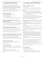
11.7 Analog Output
Figure 10. Analog Output Screen
Total of four analog outputs on connector J104:
Analog Output 1 (J104, pin 30)
Analog Output 2 (J104, pin 32)
Analog Output 3 (J104, pin 34)
Analog Output 4 (J104, pin 36)
By default, all analog outputs are turned off (function set to off).
Analog output signal range 0-10V.
Available Functions:
OFF
Pressure, logarithmic
Current, logarithmic
Current, 1V / 1nA
Current, 1V / 10nA
Current, 1V / 100nA
Current, 1V / 1uA
Current, 1V / 10uA
Current, 1V / 100uA
Current, 1V / 1mA
Current, 1V / 10mA
Current, 1V / 50mA
Voltage, 1V / 1kV
Supply Source - Selects supply driving analog output.
Options applicable to ‘Pressure, logarithmic’ and ‘Current,
Logarithmic’ functions:
Offset: Valid range from -15 to +15
Output State: Normal vs. Inverted (see examples below for details)
Logarithmic Current Example:
Current = 2X10⁻⁸ (20nA), Offset = 8, Output state = Normal
Step 1: Calculate the log of the current (Log (2X10⁻⁸) = -7.7).
Step 2: If ‘Output state = Inverted’ multiply current log value in
step 1 by (-1).
Step 3: Add the offset value (-7.7 + 8 = 0.3 Volts).
The analog output pin will read 0.3V.
Logarithmic Pressure Example:
Pressure = 1x10⁻⁹ Torr, Offset = 11, Output state = Normal
Step 1: Calculate log of pressure (Log (1x10⁻⁹) = -9)
Step 2: If ‘Output state = Inverted’ multiply current log value in
step 1 by (-1).
Step 3: Add offset value(-9 + 11 = 2V)
The analog output pin will read 2V.
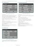
11.8 Digital Input Setup
Figure 11. Digital Input Setup Screen
Total of four digital inputs on connector J104.
Digital Input 1 (J104, pin 22)
Digital Input 2 (J104, pin 23)
Digital Input 3 (J104, pin 24)
Digital Input 4 (J104, pin 25)
By default all digital inputs are turned off (function set to off).
Available Functions:
OFF
HV Interlock
HV Switch
TSP 1 Interlock
TSP 2 Interlock
HV Interlock Function
Ground pin to satisfy interlock. If interlock is not satisfied, HV cannot
run.
HV Switch Function
Ground pin to turn on HV, otherwise HV is off.
TSP 1 Interlock Function
Ground pin to satisfy TSP 1 interlock. If interlock is satisfied, TSP 1
cannot run.
TSP 2 Interlock Function
Ground pin to satisfy TSP 2 interlock. if interlock is not satisfied, TSP
2 cannot run.
Supply Source - Selects supply that will be controlled by this setup.


