2. HORIZONTAL MODE
2-13
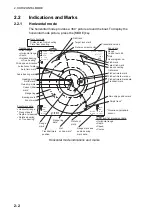
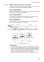
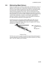
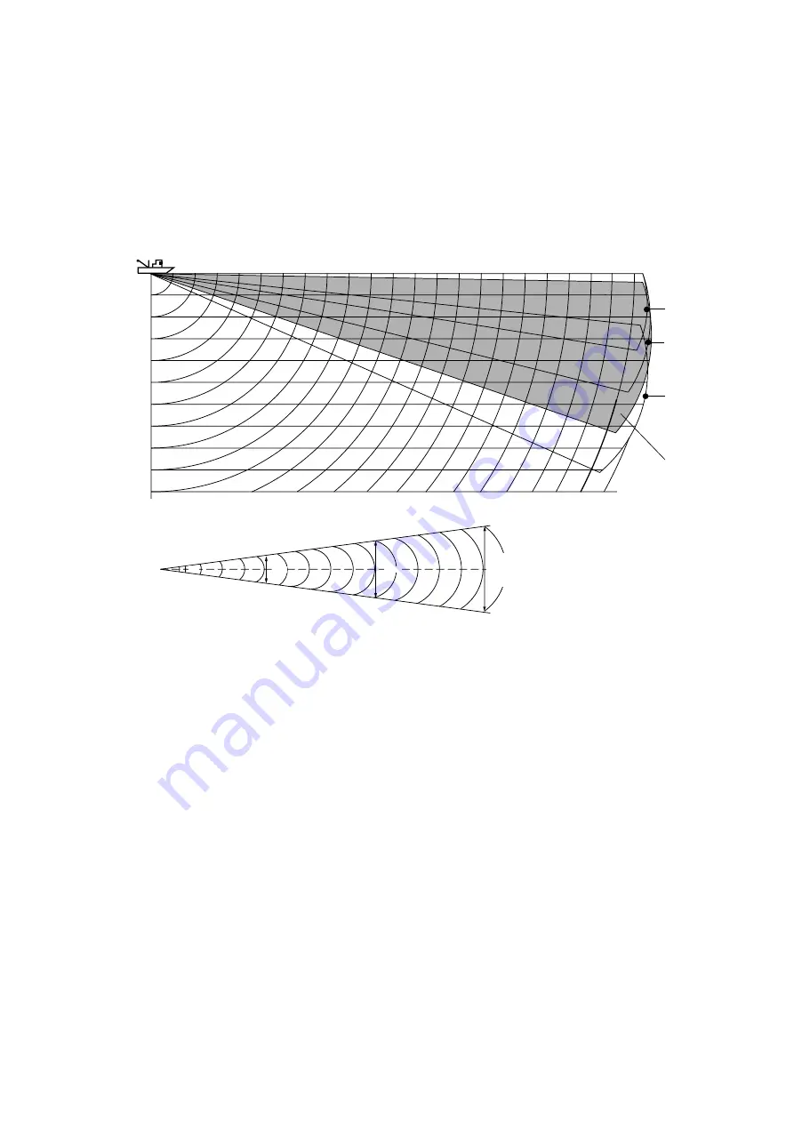
2.4.5 Suitable
tilt
angle
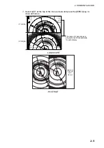
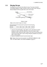
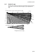
The figure below illustrates the relationship among tilt angle, depth and detection
range. Refer to it to find out the suitable tilt angle for a given depth/detection
range.
Range(m)
Vertical width of sonar beam
18
°
31 m
100 m
100 m
300 m
93 m
200 m
Depth (m)
62 m
Tilt angle and beam coverage (vertical beamwidth 18
°
at -6dB
)
100
(200)
200
(400)
300
(600)
400
(800)
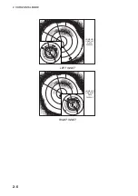
Tilt 0
˚
(0˚
‑
9˚)
20(40)
40(80)
60(120)
80(160)
100(200)
200(400)
Tilt 5
˚
(0˚
‑
14˚)
Tilt 15
˚
(6˚
‑
24˚)
Grey: Tilt 10
˚
(1˚
‑
19˚)
(-6dB)
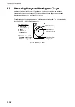
Tilt angle and beam coverage
Summary of Contents for FSV-84
Page 1: ...COLOR SCANNING SONAR FSV 84 ...
Page 6: ...SAFETY INSTRUCTIONS iv This page intentionally left blank ...
Page 34: ...1 OPERATIONAL OVERVIEW 1 18 This page intentionally left blank ...
Page 158: ...4 SLANT MODE 4 48 This page intentionally left blank ...
Page 194: ...8 CUSTOMIZING THE EQUIPMENT 8 10 This page intentionally left blank ...


