3. ADJUSTMENTS AND CHECKS
3-2
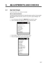
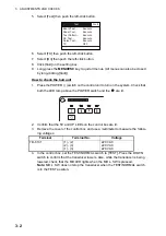
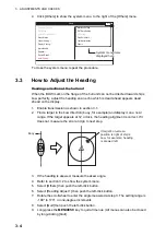
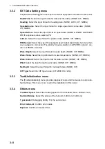
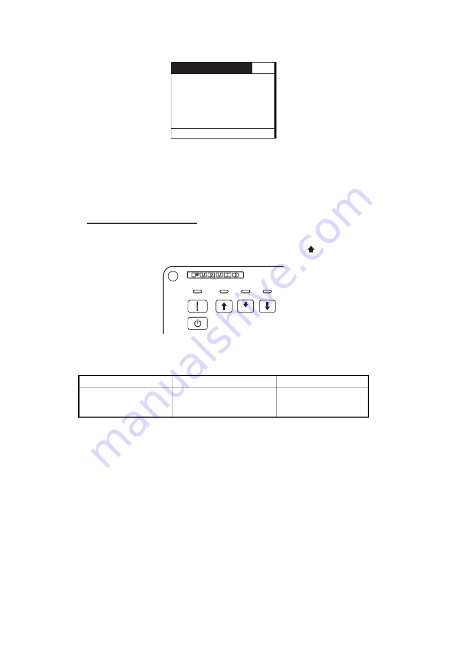
5. Select [Test] then push the left-click button.
6. Select [TX] then push the left-click button.
7. Select [On] then push the left-click button.
8. Click [Quit] on the setting box.
9. Long-press the
MENU/ESC
key to quit all menus. (All menus can also be closed
by long-clicking [Quit].)
How to check the hull unit
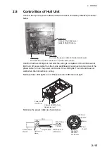
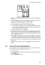
1. Press the POWER ( | ) switch on the control unit to turn on the system. Check that
both the LED lamp above the POWER switch and the
are lit.
2. Confirm that the 5V and UP LEDs on the control box are lit.
3. Remove the cover of the control box and use a multimeter to measure the follow-
ing voltages:
4. In the control box, set the TEST/NORMAL switch to [TEST]. Press the DOWN
switch to confirm that the transducer lowers. Also, while the transducer is being
lowered, check that the MD LED lights when the MD L. SW is pressed.
Note:
MD L. SW does not stop the transducer when the TEST/NORMAL switch
is in the TEST position.
Terminal
Terminal No.
Voltage
TB-C101
(1) - (2)
(2) - (3)
(1) - (3)
220 VAC
220 VAC
220 VAC
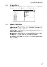
Test
Quit
Board Test...
: Execute
Panel Test...
: Execute
Test Pattern... : Execute
RX Test...
: Execute
Noise Test...
: Execute
TX :
OFF
Summary of Contents for FSV-35
Page 22: ...1 HOW TO INSTALL THE SYSTEM 1 16 This page is intentionally left blank ...
Page 55: ...D 1 13 Sep 2011 Y NISHIYAMA ...
Page 56: ...D 2 13 Sep 2011 Y NISHIYAMA ...
Page 57: ...D 3 5 Nov 2010 Y NISHIYAMA ...
Page 58: ...D 4 Y Hatai ...
Page 59: ...23 Apr 2013 Y NISHIYAMA D 5 ...
Page 60: ...23 Apr 2013 Y NISHIYAMA D 6 ...
Page 61: ...D 7 13 Sep 2011 Y NISHIYAMA ...
Page 62: ...D 8 13 Sep 2011 Y NISHIYAMA ...
Page 63: ...13 Sep 2011 Y NISHIYAMA D 9 ...
Page 64: ...13 Sep 2011 Y NISHIYAMA D 10 ...
Page 65: ...13 Sep 2011 Y NISHIYAMA D 11 ...
Page 66: ...D 12 13 Sep 2011 Y NISHIYAMA ...

