2. WIRING
2-16
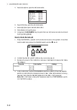
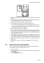
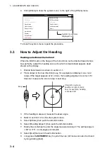
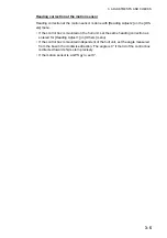
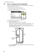
2.9
Input Voltage and Fuses
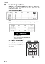
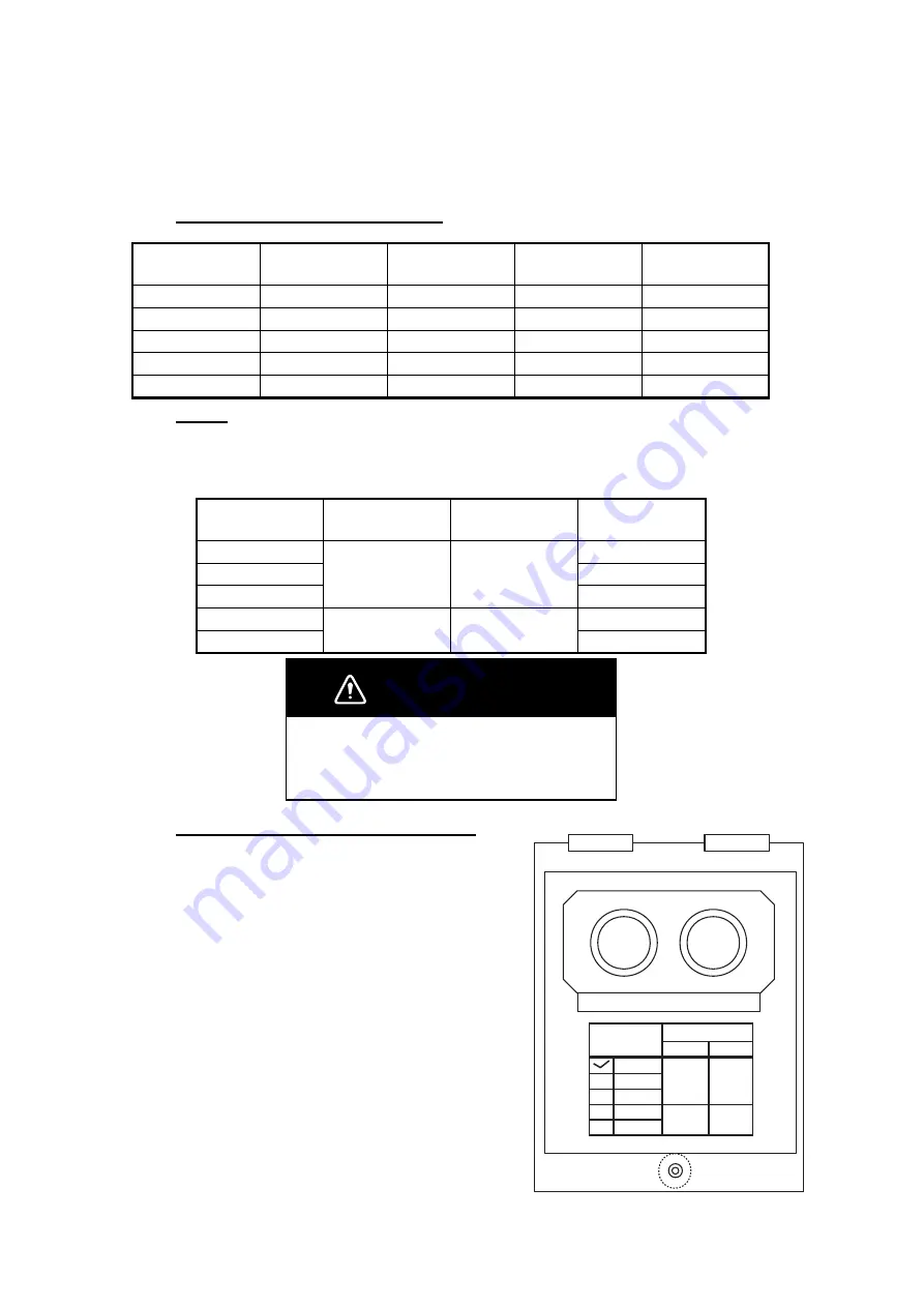
The transceiver unit is shipped from the factory with its input voltage set for 230 VAC
and a 10 A fuse inserted in F601 and F602. For other voltages, change toggle switch
positions and fuses shown below.
Input voltage and toggle switch
Fuses
Change the fuse in F601 and F602 according to input voltage, referring to the table
below.
How to mark the input voltage label
After setting toggle switches and changing
the fuses, mark the label on the inside of the
cover with the voltage that applies. In the ex-
ample shown below, 100 V is checked; 20 A
fuses are used.
Input voltage
S603
S604
S605
Default
setting
100 VAC
L
L
L
-
110 VAC
H
L
L
-
115 VAC
H
H
L
-
220 VAC
H
L
H
-
230 VAC
H
H
H
Default
Input Voltage
(TB-B101)
F601
F602
Default
setting
100 VAC
20A
20A
-
110 VAC
-
115 VAC
-
220 VAC
10A
10A
-
230 VAC
Default
WARNING
Use the proper fuse.
Use of a wrong fuse can result in damage to the
equipment or cause fire.
FUSE FUSE
F601 F602
INPUT
(TB-B101)
FUSE
F601 F602
100V
110V 20A 20A
115V
220V
230V
10A 10A
Summary of Contents for FSV-35
Page 22: ...1 HOW TO INSTALL THE SYSTEM 1 16 This page is intentionally left blank ...
Page 55: ...D 1 13 Sep 2011 Y NISHIYAMA ...
Page 56: ...D 2 13 Sep 2011 Y NISHIYAMA ...
Page 57: ...D 3 5 Nov 2010 Y NISHIYAMA ...
Page 58: ...D 4 Y Hatai ...
Page 59: ...23 Apr 2013 Y NISHIYAMA D 5 ...
Page 60: ...23 Apr 2013 Y NISHIYAMA D 6 ...
Page 61: ...D 7 13 Sep 2011 Y NISHIYAMA ...
Page 62: ...D 8 13 Sep 2011 Y NISHIYAMA ...
Page 63: ...13 Sep 2011 Y NISHIYAMA D 9 ...
Page 64: ...13 Sep 2011 Y NISHIYAMA D 10 ...
Page 65: ...13 Sep 2011 Y NISHIYAMA D 11 ...
Page 66: ...D 12 13 Sep 2011 Y NISHIYAMA ...

