

2. WIRING
2-2
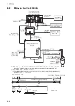
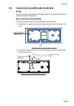
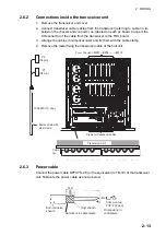
2.2
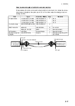
How to Connect Units
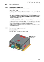
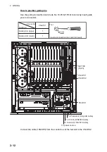
PROCESSOR UNIT
FSV-3503 (FSV-35)/
FSV-3503S (FSV-35S)
12-24 VDC
DPYC-6
DVI-D/D LINK
(5m /10 m)
MONITOR
(local supply)
CONTROL UNIT
FSV-8501
TRANSCEIVER UNIT
FSV-351
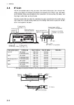
IF UNIT
FSV-8502
19S1050 (3 m)
10S2380
(Max. length 100 m)
FR-FTPC-CY
䋨
Max. length 100 m
䋩
10S2884
5m/10m
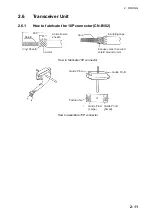
*1: The same type of connector is fitted at each end of the cable, the connector where the
amount of sheath removed is greater should be connected to the transceiver unit.
*2: The details of the cable is shown below.
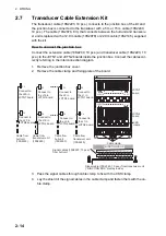
*3: When using cable for extension kit, the length of the cable between the transceiver unit
and the hull unit is 10 m or 20 m.
HULL UNIT
FSV-303
(1200 mm stroke)
FSV-304
(1600 mm stroke)
10S2223
(effective length: 5 m, 10 pcs.)
10S2078 (8m)
220 VAC
3
φ
, 50-60Hz
TPYCY-4
*1 *2 *3
*2 *3
100/110/115/
220/230 VAC
1
φ
, 50-60Hz
DPYCYS-2.5
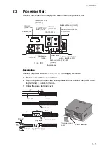
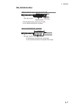
10S2223
60
1400
P2
(40 pin)
P1
(34 pin)
Transceiver Unit side
VV-SBCJ-0.3x14P (10S2078)
38
720
28
7
7
(unit
䋺
cm)
Hull Unit or Processor Unit side
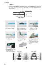
Clamp point
Clamp point
Clamp point
SUB CONTROL UNIT
FSV-853 (option)
USB cable
Summary of Contents for FSV-35
Page 22: ...1 HOW TO INSTALL THE SYSTEM 1 16 This page is intentionally left blank ...
Page 55: ...D 1 13 Sep 2011 Y NISHIYAMA ...
Page 56: ...D 2 13 Sep 2011 Y NISHIYAMA ...
Page 57: ...D 3 5 Nov 2010 Y NISHIYAMA ...
Page 58: ...D 4 Y Hatai ...
Page 59: ...23 Apr 2013 Y NISHIYAMA D 5 ...
Page 60: ...23 Apr 2013 Y NISHIYAMA D 6 ...
Page 61: ...D 7 13 Sep 2011 Y NISHIYAMA ...
Page 62: ...D 8 13 Sep 2011 Y NISHIYAMA ...
Page 63: ...13 Sep 2011 Y NISHIYAMA D 9 ...
Page 64: ...13 Sep 2011 Y NISHIYAMA D 10 ...
Page 65: ...13 Sep 2011 Y NISHIYAMA D 11 ...
Page 66: ...D 12 13 Sep 2011 Y NISHIYAMA ...


