

1. HOW TO INSTALL THE SYSTEM
1-10
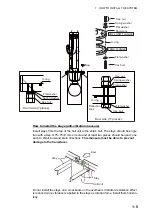
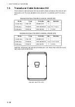
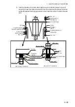
2. Make holes for four self-tapping screws (M5x20).
3. Peel the tape from the F mount gasket then attach the gasket to the rear of the
control unit.
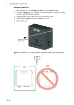
4. Connect a ground wire (1.25sq, local supply) between the ground terminal at the
bottom of the unit and ship’s ground.
5. Set the unit to the cutout and fasten it with four self-tapping screws (M5x20) and
wave washers.
6. Set cosmetic caps to fixing holes.
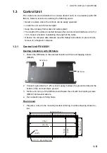
1.3.2
Sub Control Unit FSV-853 (option)
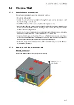
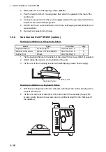
Desktop installation, with keyboard fixture
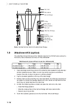
1. Fix the keyboard fixture to the bottom of the unit with the screws (M4x12) supplied.
2. Attach rubber feet (2 pcs.) to the bottom of the unit.
3. Fix the unit to the mounting location with self-tapping screws (local supply).
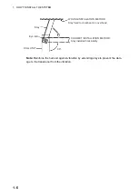
Desktop installation, no keyboard fixture
1. Drill four mounting holes of 5 mm diameter, referring to the outline drawing at the
back of this manual.
2. Fix the unit with four screws (M4) from under side of the desktop. (Supply the
screws locally. Be sure the screws are of a sufficient length for the thickness of
the desktop.)
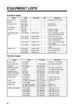
Name
Type
Code No.
Qty
Keyboard fixture
03-163-7821-1
100-306-291-10
1
Washer head screw
M4x12 C2700W MBN12
000-163-192-10
6
Rubber foot
M5x40
000-162-682-10
2
Keyboard fixture
Rubber feet
Summary of Contents for FSV-35
Page 22: ...1 HOW TO INSTALL THE SYSTEM 1 16 This page is intentionally left blank ...
Page 55: ...D 1 13 Sep 2011 Y NISHIYAMA ...
Page 56: ...D 2 13 Sep 2011 Y NISHIYAMA ...
Page 57: ...D 3 5 Nov 2010 Y NISHIYAMA ...
Page 58: ...D 4 Y Hatai ...
Page 59: ...23 Apr 2013 Y NISHIYAMA D 5 ...
Page 60: ...23 Apr 2013 Y NISHIYAMA D 6 ...
Page 61: ...D 7 13 Sep 2011 Y NISHIYAMA ...
Page 62: ...D 8 13 Sep 2011 Y NISHIYAMA ...
Page 63: ...13 Sep 2011 Y NISHIYAMA D 9 ...
Page 64: ...13 Sep 2011 Y NISHIYAMA D 10 ...
Page 65: ...13 Sep 2011 Y NISHIYAMA D 11 ...
Page 66: ...D 12 13 Sep 2011 Y NISHIYAMA ...


