background image

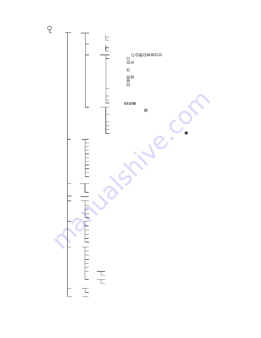
APPENDIX 1 MENU TREE

AP-3

  System

2

User

User Color (Adjust RGB for each color. The setting range for each color is 0 - 63.)

User Clutter (Color 1 -8: 1 - 50; 

6

)

[User1]

[User2]

Screen Layout (    ,    ,    ,    ,    ,    ,    ,     )
Disp Mode (    : 

HF

, LF, HZm, LZm, Mix

                        ,    : 

HZm+HF

, LZm+LF, LF+HF, LZm+HZm,

                                HF+Mix, LF+Mix, HF2+HF1, LF2+LF1
                        : 

HZm+HF

, LZm+LF, LF+HF, LZm+HZm,

                          HF+Mix, LF+Mix
                        ,    : LF+HZm+HF, LZm+LF+HF, 

LF+HF+Mix

                        : LZm+LF+HZm+HF
                        : 

HZm+HF

, LZm+LF)

Zoom Mode (Bottom Lock, 

Bottom Zoom

, Marker Zoom,

                       Discrim1/2, Discrim1/3)
Target Echo (

Normal

, Surface, Squid, Deep Sea)

Nav Data Disp (

Off

, Small, Large)

Nav Data (    ,    ,    )

Screen Layout (Same choices as Screen Layout in User1.
                           Default is     .)
Disp Mode (Same choices as User1.
                     Default is 

LZm+LF+HZm+HF

.)

Zoom Mode (Same choices and default setting as Zoom Mode in User1.)
Target Echo (Same choices and default setting as Target Echo in User1.)
Nav Data Disp (Same choices as Nav Data Disp in User1.)
Nav Data (Same choices as Nav Data in User1. Default is     .)

Range

Range 1 (16 - 9000 ft; 

30 ft

)

Range 2 (16 - 9000 ft; 

60 ft

)

Range 3 (16 - 9000 ft; 

120 ft

)

Range 4 (16 - 9000 ft; 

250 ft

)

Range 5 (16 - 9000 ft; 

500 ft

)

Range 6 (16 - 9000 ft; 

1000 ft

)

Range 7 (16 - 9000 ft; 

1600 ft

)

Range 8 (16 - 9000 ft; 

3000 ft

)

Zoom Range (16 - 600 ft; 

16 ft

)

B/L Range (16 - 600 ft; 

16 ft

)

Split Range (

Off

, On)

Key

FUNC Key (Pic. Advance, Interference, Color Erase, Clutter, White Line, White Marker, 

TVG

,

                     STC, Bottom Zone, A-Scope, Split Range, Auto Shift, Freq Choice, Freq Control)

Key Beep (Off, 

On

Lang

Language (

English

, OTHERS)

Units

Depth (m, 

ft

, fa, HR, pb)

Temp (

°

C, 

°

F

)

Speed (

kt

, km/h, mph)

Wind (

kt

, km/h, mph, m/s)

Distance (

nm

, km, sm)

NMEA

NMEA0183 (Ver 1.5, 

Ver 2.0

, Ver 3.0, Special)

NMEA Port (

In/Out

, In/In)

NMEA Output (

Off

, On)

WAAS Setup (

Off

, WAAS-00 - WAAS-27)

TLL Output (Off, 

TLL

, FURUNO-TLL)

Port Monitor (Set up data ports, by installer.)

Calib.

Sound Speed (200.0 - 2000.0 m/s; 

1500.0 m/s

)

Temp (-20.0

°

F - +20.0

°

F; 

+0.0 

°

F

)

Speed (STW) (-50 - +50%; 

+0%

)

Bottom Level (-100 - 100; 

0

)

Zero Line (Off, 

On

)

Zero Line Area (4.5 - 9.8 ft; 

4.5 ft

)

[HF]

[LF]

Tests

Test

LCD Test 

Reset

Factory Reset (Yes, 

No

)

Draft (-15.0 - +50.0 ft, 

+0.0 ft

)

Gain ADJ (-20 - +20, 

+0

)

Draft (-15.0 - +50.0 ft, 

+0.0 ft

)

Gain ADJ (-20 - +20, 

+0

)

Default (Yes, 

No

)

Custom (Yes, 

No

)

Default (Yes, 

No

)

Custom (Yes, 

No

)

Summary of Contents for FCV-295

Page 1: ...COLOR LCD SOUNDER FCV 295 OPERATOR S MANUAL www furuno co jp MODEL ...

Page 2: ...horized Distributor Dealer 9 52 Ashihara cho Nishinomiya 662 8580 JAPAN Telephone 81 0 798 65 2111 Fax 81 0 798 65 4200 A MAY 2008 Printed in Japan All rights reserved Pub No OME 23760 A 00016850810 00016850810 AKMU FCV 295 00016850810 00016850810 0 0 0 1 6 8 5 0 8 1 0 ...

Page 3: ...s shown in this manual may not match the screens you see on your display The screen you see depends on your system configuration and equipment set tings Store this manual in a convenient place for future reference FURUNO will assume no responsibility for the damage caused by improper use or modification of the equipment including software by an unauthorized agent or a third party When it is time t...

Page 4: ...If you feel that the equipment is acting abnormally immediately turn off the power at the switchboard If the equipment is excessively warm or making strange noises immediately turn off the equipment at the switch board Keep the equipment away from rain and water splash Fire electrical shock or injury can result if water leaks into the equipment Use the proper fuse Use of an incorrect fuse can dama...

Page 5: ...ile the picture advance speed is set to stop The depth indication is not refreshed while the picture is stopped Use of depth data for navigation in this case could lead to grounding or other dangerous situation Do not handle the LCD s panel roughly it is made of glass Injury can result if the glass breaks CAUTION CAUTION WARNING To avoid electrical shock do not remove cover No user serviceable par...

Page 6: ...5 1 17 1 Using the FUNCTION control 15 1 17 2 Programming the FUNCTION control 15 1 18 Waypoints 16 1 18 1 Entering a waypoint 16 1 18 2 Editing waypoints 17 1 18 3 Erasing waypoints 17 1 18 4 Setting destination waypoint 18 1 19 Menu Description 18 1 19 1 Sounder menu 18 1 19 2 Tx Rx menu 22 1 19 3 Display menu 22 1 19 4 Data menu 23 2 SYSTEM MENU 25 2 1 How to Open the System Menu 25 2 2 User Me...

Page 7: ...isplays underwater conditions on a 10 4 inch color LCD in various colors according to echo strength The main features of the FCV 295 are FURUNO Free Synthesizer FFS trans ceiver design allows use of user selectable operating frequencies 64 color including background presenta tion provides detailed information on fish density and bottom composition Automatic operation selects correct range and gain...

Page 8: ...s shown below with solid line Low Freq Transducer High Freq Transducer Navigation Equipment DISPLAY UNIT CV 295 Power 12 24 VDC Rectifier PR 62 100 110 115 220 230 VAC 1φ 50 60 Hz Water Temp Sensor T 02MSB etc Water Temp Speed Sensor ST 02MSB etc ...

Page 9: ...auto gain is active 7 ENTER STWX Cursor pad Select items on menus Change settings Move VRM Inoperative when Nav Data is displayed Push ENTER key to confirm setting 8 MENU ESC Open close menu Escape from current operation 9 BRILL Turn power on momentary push and off long push Open display brilliance setting window with power turned on 10 MARK Record position of an important echo as a waypoint Outpu...

Page 10: ...ith the maximum brilliance Adjust the brilliance as necessary 1 4 Selecting a Display The FCV 295 has seven display modes low frequency display high frequency display dual frequency display low frequency zoom high frequency zoom user 1 display and user 2 display Select one with the MODE control as follows 1 Rotate the MODE control to open the mode selection window 2 Rotate the MODE control to sele...

Page 11: ... is expanded onto the left half of the screen This mode is useful for detecting bottom fish Note 1 The range of the zoom display can be adjusted on the Range menu Note 2 The zoom marker can be turned on or off on the Display menu Depth Display mode Picture advance speed Color bar Alarm icon 1 2 P R AUTO Minute marker Displayed Not displayed every 30 minutes Range mode Depth scale 0 0 Zero line 20 ...

Page 12: ... screen The bot tom discrimination display shows the bottom as a straight line which is useful for determin ing bottom hardness Bottom discrimination 1 3 display This display is similar to the bottom discrimi nation 1 2 display except the bottom discrimi nator display occupies the bottom one third of the left half of the screen as below Zoom marker Zoom marker automatically follows change in depth...

Page 13: ...lect Off or On as appro priate On The range is automatically changed to keep the bottom echo on the lower half of the screen Range shift and gain are in operative when Auto Range is active AUTO_R is shown at the top left corner on the screen Off The range may be chosen from eight basic ranges MANUAL is shown at the top left corner on the screen 3 Press the ENTER key to save the set ting 1 5 2 Manu...

Page 14: ...t of as providing a window into the water column and range shifting as moving the window to the desired depth Note This function is inoperative when the Auto Range or Auto Shift is active 1 Press S or T on the SHIFT key to show the Shift setting window 2 Use S or T on the SHIFT key to select the amount of shift desired 3 Press the MENU ESC key to close the window or wait six seconds to automati ca...

Page 15: ... top left corner on the screen Cruising This mode clearly displays stronger echoes for example bottom and suppresses weak echoes Use it for general cruising H L AC is shown at the top left corner on the screen Off Select to manually adjust gain 3 For automatic operation Fishing or Cruis ing use the auto gain offset range 5 to 5 with W or X 4 Press the ENTER key 1 7 2 Manual gain adjustment The GAI...

Page 16: ...vely you can press X The cursor yellow shifts to the menu item window right and the color of the bar at the top of the menu item window changes from gray to blue to indicate that the menu item window is ac tive 4 Use S or T to select a menu item and press the ENTER key The menu item s setting box or setting window appears 5 Use S or T to select an option 6 Press the ENTER key or W to save the sett...

Page 17: ...he window indicate the number of scan lines produced per transmission 1 16 is the slowest speed and 4 1 is the fastest speed 1 16 means one scan line is produced every 16 trans missions Stop freezes the display and is useful for taking a photo of the display 5 Press the MENU ESC key twice to fin ish Note The picture advance direction is select able See sec 1 19 3 1 11 Rejecting Interfer ence Inter...

Page 18: ...feature 1 Press the MENU ESC key to open the menu 2 Use S or T to select Sounder and press the ENTER key 3 Use S or T to select Color Erase and press the ENTER key 4 Use S or T to select the color to erase and press the ENTER key The setting range is 0 to 50 in intervals of 5 The larger the setting value the greater the number of colors that are erased 5 Press the MENU ESC key twice to close the m...

Page 19: ...dow 1 14 Adjusting TVG A fish school at a deep depth is displayed in weak colors even if it is equal in strength to one in shallow waters This is due to propaga tion attenuation of the ultrasonic wave To compensate for this difference use TVG TVG automatically adjusts the gain with depth so that echoes of the same strength and dif ferent depths are shown in the same colors regardless of their dept...

Page 20: ...t each transmis sion with amplitudes and tone proportional to their intensities on the right side of the screen It is useful for estimating the type of fish school and bottom composition Note In the horizontal split dual frequency display the A scope display appears on both high and low frequency displays In the verti cal split dual frequency display the A scope display only appears on the high fr...

Page 21: ... bottom lock and bottom discrimination 1 2 or 1 3 displays must be turned on to use this alarm Water temperature alarm The water tem perature alarm alerts you when the water tem perature is within inside alarm the alarm range set or under over outside alarm the range set Speed alarm The speed alarm alerts you when the ship s speed is within inside alarm or under over outside alarm the preset speed...

Page 22: ...n case of Arrival and press the ENTER key 11 Use S or T to set the range of depth temperature speed or distance as appro priate To shorten the alarm range marker use S and to lengthen it use T 12 For the bottom alarm temperature alarm speed alarm or arrival alarm press the ENTER key to finish and then go to step 16 For a fish alarm press the ENTER key and go to step 13 13 Use S or T to select Fish...

Page 23: ...req Control 1 17 1 Using the FUNCTION control 1 Press the FUNCTION control to open the setting window registered This win dow can also be opened by rotating the control 2 Change setting as applicable 1 17 2 Programming the FUNC TION control 1 Push and hold down the FUNCTION control until the FUNC key setting window appears 2 Use S or T or rotate the FUNCTION control to select the item you want to ...

Page 24: ...he MARK or the ENTER key to save the position A red vertical line ap pears at the position The waypoint is named automatically with the next se quential waypoint number If you want to change the waypoint name go to step 4 Otherwise go to step 6 Note 1 When TLL or FURUNO TLL is selected at TLL Output on the NMEA menu of the System menu the latitude and longitude position at the cursor posi tion is ...

Page 25: ...open the menu 2 Use S or T to select Data and press the ENTER key 3 Use S or T to select WPT List and press the ENTER key 4 Use S or T to select the waypoint to edit and press the ENTER key The way point setting window appears 5 Use S or T to select the item to edit 6 Edit item as appropriate 7 Press the MENU ESC key several times to close the window 1 18 3 Erasing waypoints A waypoint currently s...

Page 26: ...ion 1 2 1 3 when zoom is selected with the MODE control Free Shift Turn on off independent range shift Select Off to apply the same shift value to all ranges To set range shift independently on each range select On This feature is in operative when auto range or auto shift is ac tive Auto Shift Turn the auto shift feature on or off Select Off to shift the display manually with S or T On automatica...

Page 27: ...can register frequencies between 66 kHz and 109 kHz The frequencies registered here may be selected at Freq Choice in the Sound er menu Set transducer frequency keeping in mind these considerations Set frequency which is suitable for detect ing targeted fish Shift frequency so as to reduce interfer ence Lower frequency to increase detection range Raise frequency to improve resolution 1 Choose Freq...

Page 28: ...is not only use ful for discriminating bottom fish but is also valuable for judging fish school density The setting range is 0 100 in intervals of 10 The higher the value the thicker the line 1 Select White Line and press the ENTER key 2 Use S or T to set the width and press the ENTER key The higher the figure the wider the width of the line The option Edge paints a very thin line above the bottom...

Page 29: ... the STC too high fish echoes near the surface may be erased Smoothing If echoes appear like patch work turn this feature on to smooth them Bottom Zone Select the area where to show the bottom echo when Auto Range is active 1 Choose Bottom Zone and press the EN TER key 2 Use W or X to select the boundary line to adjust 3 Use S or T to adjust the boundary line Bottom Search Select the frequency to ...

Page 30: ...ct a long pulse length For better resolution choose a shorter pulse Short 1 raises the detection resolution however detection range is short er pulse length is about 1 4 of Std than the Std setting Short 2 raises the detection reso lution however detection range is shorter pulse length is about 1 2 of Std than the Std setting Std is the standard pulse length and is suitable for general use Long In...

Page 31: ... or off Hue Change the color arrangement The choices are Std Hue1 thru Hue6 and Cus tom As you move through the selections you can see the color arrangement at the right side of the screen Background Change the background to suit your current environment The choices are white light blue blue dark blue and black This feature is inoperative when Hue is select ed to Custom Colors Select the number of...

Page 32: ...ect source of position data among Auto GPS and Loran C Auto selects navigator in order of accuracy in case of mul tiple navigators The order is GPS followed by Loran C Wind Spd Dir Display wind speed and direc tion data in True or Apparent The apparent wind is the actual flow of air acting upon a sail or the wind as it appears to the sailor The true wind is the wind seen by a stationary ob server ...

Page 33: ...he color to adjust and press the ENTER key The RGB ad justment window appears 3 Press S or T to select the color to adjust 4 Press W or X to adjust color 0 63 5 Press the ENTER key to finish setting 6 To enable user colors press S or T sev eral times to select Custom at the bottom of the color bar and then press the EN TER key 7 Press S or T to select Yes and then press the ENTER key Hue on the Di...

Page 34: ... show The choices depend on the setting of Screen Layout The screen modes are shown as follows HF High Frequency LF Low Frequency Zm Zoom Mix Mix display HF1 HF2 LF1 LF2 1 and 2 show the same picture Gain can be adjusted independently for each If you want to then set emphasize strong colors reddish brown red Strong color Color 6 Large value Color 5 to Color 1 Small value emphasize middle colors ye...

Page 35: ...splay Target Echo Set fishing objective Normal is for general purpose fishing Surface is for de tecting surface fish Pulse repetition rate is higher than Normal on the 1kW and 2kW transducers that are programmed into the menu Squid detects squid and other individ ual fish These items are automatically set Tx Pulse Short 1 Echo Stretch ON and Smoothing Off Deep Sea is the same as Normal Nav Data Di...

Page 36: ...meter water temperature air pressure time to go to destination waypoint XTE speed SOG Items displayable in 4 9 depth position speed SOG speed STW course range and bearing trip meter odometer water temperature heading wind speed wind direction air pressure time to go to destination waypoint XTE Graphic display XTE XTE 0 20nm 27 3nm Rng PORT SPEED SOG SPEED STW WIND WPT COMPASS HEADING SOG Speed ove...

Page 37: ...arker zoom and bottom zoom displays Press S or T to set zoom range as desired For the hor izontal split screen the range is one half the value set B L Range Set display range for bottom lock and bottom discrimination displays Use S or T to set B L range as desired For the horizontal split screen the range is one half the value set Split Range Split range enables disables independent ad justment of...

Page 38: ...epth m ft fa HR pb Temperature C F Speed kt km h mph Wind kt km h mph m s Distance nm km sm 2 7 Calib Menu Sound Speed Adjust the sound velocity of the Tx Rx signal if the depth indication is incorrect because of water temperature or salinity density Temp If the water temperature indication is wrong you can apply an offset to it to correct it Refer to the installation manual Speed STW If the speed...

Page 39: ...eristics If the width of the transmission line is 4 5 ft default value or more set the transmission line width with Zero Line Area as follows Zero Line Area This feature adjusts the rejection width of the transmission line from the area specified when the menu item Zero Line is turned off The effective range is 4 5 to 9 8 ft For a long tail increase the value If the transmission line does not disa...

Page 40: ...ne for cleaning Al so do not use degreaser or antifog solution as they can strip the coating from the LCD 3 3 Transducer Main tenance Marine life on the transducer face will result in a gradual decrease in sensitivity Check the transducer face for cleanliness each time the boat is dry docked Carefully remove any ma rine life with a piece of wood or fine grade sandpaper WARNING ELECTRICAL SHOCK HAZ...

Page 41: ...me Type Code No Lamp holder complete set 104LHS46 000 160 949 10 Icon Meaning Voltage is lower than 10 VDC If the voltage goes be low 9 V the equipment auto matically shuts itself off Voltage is higher than 33 VDC If the voltage goes higher than 34 V the equip ment automatically shuts it self off Symptom Remedy Possible cause Neither echo nor fixed range scale appears Check battery voltage Check f...

Page 42: ...s Push each key The key s on screen location turns red or white alternately and a beep sounds with each push FUNCTION GAIN and RANGE con trols Rotate the control while observing its on screen location Clockwise rotation in creases the value counterclockwise rota tion decreases it Next push the control Its on screen location turns red or white alter nately and a beep sounds with each push MODE cont...

Page 43: ...ress the MENU ESC key twice to close the menu 3 10 Restoring Default Settings You may wish to restore default settings to start afresh 1 Press the MENU ESC key to open the menu 2 Press S or T to select Reset at the bot tom of the menu bar and press the EN TER key to show the Reset menu 3 Press the ENTER key again The confir mation window appears 4 Press S to select Yes and then press the ENTER key...

Page 44: ...ne Select are where to show bottom echo Bottom Search Auto LF HF Echo Stretch Off On 1 Bold Italic Default HF Clutter 0 100 40 HF Curve Std Linear H L S Custom LF Clutter 0 100 40 LF Curve Std Linear H L S Custom White Line Color White RGB adjustable Default Yes No HF TVG Level 1 8 4 HF TVG Distance 100 3000 ft 600 ft LF TVG Level 1 8 4 LF TVG Distance 100 3000 ft 600 ft HF STC 0 10 0 LF STC 0 10 ...

Page 45: ...h Level Weak Medium Strong Temperature Off Inside Outside From 20 0 110 0 F 65 0 F Span 0 1 30 0 F 1 0 F Speed Off Inside Outside From 0 0 99 0 kt 0 0 kt Span 1 0 50 0 kt 1 0 kt Arrival Alarm Off Inside Outside Radius 0 01 99 99 nm 0 01 nm B L mode only 2 Data Go to WPT Off Destination 1 20 WPT List Data Box 1 Speed SOG Off On Speed STW Off On Depth Off On Range Off On Bearing Off On Position Off ...

Page 46: ... Range 2 16 9000 ft 60 ft Range 3 16 9000 ft 120 ft Range 4 16 9000 ft 250 ft Range 5 16 9000 ft 500 ft Range 6 16 9000 ft 1000 ft Range 7 16 9000 ft 1600 ft Range 8 16 9000 ft 3000 ft Zoom Range 16 600 ft 16 ft B L Range 16 600 ft 16 ft Split Range Off On Key FUNC Key Pic Advance Interference Color Erase Clutter White Line White Marker TVG STC Bottom Zone A Scope Split Range Auto Shift Freq Choic...

Page 47: ...APPENDIX 2 SCREEN LAYOUT The screen may be divided as desired with Screen Layout on the User menu No split HIGH NORMAL LOW NORMAL HIGH ZOOM HF Normal LF Normal HF Zoom LOW ZOOM MIX NORMAL LF Zoom MIX Normal ...

Page 48: ...ard and 2 3 upward HF Zm Nor LF Zm Nor LF HF LF Zm HF Zm HF MIX LF MIX H Z O O M H N O R M A L HIGH NORMAL HIGH ZOOM L Z O O M L N O R M A L LOW NORMAL LOW ZOOM L N O R M A L H N O R M A L HIGH NORMAL LOW NORMAL L Z O O M H Z O O M HIGH ZOOM LOW ZOOM H N O R M A L M I X N O R HIGH NORMAL MIX NORMAL L N O R M A L M I X N O R LOW NORMAL MIX NORMAL H2 H1 H NORMAL1 H NORMAL2 L2 L1 L NORMAL1 L NORMAL2 ...

Page 49: ... HF LF HF MIX L N O R M A L H N O R M A L H Z O O M HIGH NORMAL HIGH ZOOM LOW NORMAL L N O R M A L H N O R M A L L Z O O M HIGH NORMAL LOW NORMAL LOW ZOOM L N O R M A L H N O R M A L M I X N O R MIX NORMAL HIGH NORMAL LOW NORMAL LF Zm Nor HF Zm Nor LOW NOR HIGH NOR LOW ZOOM HIGH ZOOM ...

Page 50: ...tical division LOW HIGH LF or HF DUAL HIGH LOW ZOOM ZOOM LOW LOW LOW HIGH HIGH LOW ZOOM NORMAL A SCOPE ON A S C O P E A S C P A S C P A S C P A S C P ZOOM ZOOM HIGH HIGH ZOOM A S C P A S C P LOW HIGH LF or HF DUAL LOW HIGH ZOOM ZOOM LOW NORMAL LOW HIGH A SCOPE ON LOW HIGH Z O O M L O W A S C O P E A S C O P E A S C O P E ZOOM ZOOM HIGH Z O O M H I G H A S C O P E ...

Page 51: ...tion 2 8 Picture advance speed 7 steps Lines TX Stop 1 16 1 8 1 4 1 2 1 1 2 1 4 1 Synchronize w ship s speed 2 9 Alarm Fish Normal Bottom Water temperature Bottom Ship s speed arrival 2 10 Noise limiter Frequency adjustable as transducer 2 11 Automatic indication Automatic gain adjust fishing cruising Automatic range shift Water temperature graph optional sensor required 3 INTERFACE 3 1 Number of ...

Page 52: ...ion 23 Display selection 2 Draft 31 Dual frequency display 3 E Echo stretch 21 F Fish bottom alarm 13 Fish normal alarm 13 Free shift 18 Frequency control 19 Frequency preset 19 FUNCTION control 15 Fuse replacement 33 G Gain adjustment 7 Gain adjustment 31 GAIN control 7 H Header info 23 I Interference rejector 9 K Key menu 29 L Language menu 30 LCD Backlight Life 33 LCD test 35 M Maintenance 32 M...

Page 53: ...6 description 5 User clutter 26 User color 25 User menu 25 V VRM 8 W Water temperature alarm 13 Water temperature graph 23 Water temperature graph color 23 Water temperature offset 30 Water temperature source 24 Waypoints destination waypoint 18 editing 17 entering 16 erasing 17 White line 20 White marker 20 Wind speed indication 24 Window color 23 Z Zero line 31 Zoom marker 23 Zoom mode preset 18...

Reviews: