9-1
9. PROCESSOR UNIT CSH-835
(BLACKBOX TYPE FOR CSH-83)
9.1 Installing the Unit
When selecting a mounting location, consider the following conditions:
•
Place where operating personnel are able to control the unit easily while observing the
fishing ground or the area surrounding the vessel.
•
Place not exposed to direct sunlight, water splashes or hot air.
•
Place where maintenance and ventilation clearance shown in the outline drawings is
ensured.
•
Observe the compass safe distances shown on page i to prevent interference to a
magnetic compass.
Mounting procedure
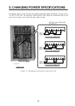
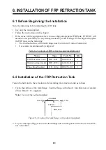
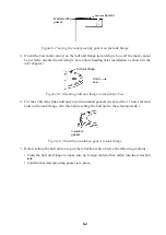
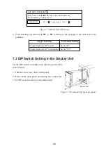
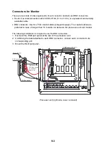
1. Remove the mounting base by unscrewing the two bolts at the front bottom.
2. Fix the mounting base to the table or deck by using six self-tapping screws 6x20
(supplied).
3. Place the unit on the mounting base, slide it forward and then fasten it to the mounting
base with two bolts.
210
±
1
(90
°
)
6-
φ
8 Fixing holes
(133)
7
220
37
210
±
1
14
0
±
1
Remove two bolts
Processor unit
Top view
Summary of Contents for CSH-83
Page 1: ...COLOR SCANNING SONAR MODEL CSH 83 84 Back ...
Page 6: ...This page is intentionally left blank ...
Page 11: ...3 2 Heater Heat insulator Figure 3 2 Typical sonar compartment ...
Page 68: ...A 10 ...
Page 77: ...A 19 ...
Page 78: ...A 20 ...
Page 79: ...A 21 ...
Page 80: ...A 22 ...
Page 81: ...A 23 ...
Page 82: ...A 24 ...
Page 83: ...A 25 ...
Page 84: ...A 26 ...
Page 85: ...D 1 ...
Page 86: ...D 2 ...
Page 87: ...Y Hatai D 3 ...
Page 88: ...D 4 ...
Page 89: ...Oct 31 03 D 5 ...
Page 90: ...Dec 10 02 D 6 ...
Page 91: ...D 7 ...
Page 92: ...D 8 ...
Page 93: ...D 9 ...
Page 94: ...D 10 ...
Page 95: ...D 11 ...
Page 96: ...D 12 ...
Page 97: ...D 13 ...
Page 98: ...D 14 ...
Page 99: ...D 15 ...
Page 100: ...D 16 ...
Page 101: ...D 17 ...
Page 102: ...D 18 ...
Page 103: ...D 19 ...
Page 104: ...D 20 ...

