4-5
Positioning guide pins
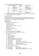
The guide pins of the connector identify the mating receptacle. Position them as shown in the
table below.
Table 4-1 Connectors CN-A1, CN-A5, J201 and guide pins
Connector
Guide Pin
CN-A1
CN-A5
J201
Guide Pin Setting Tool
Guide Pin A (Large)
1
5
1
Type 10-910-0179-0
Guide Pin B (Small)
1
1
1
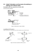
Clamping the cable
Fix the cable in the clamp where shield is folded back onto the armor.
Cable clamp
armor
Anticorrosive sheath
Figure 4-6 Clamping the cable
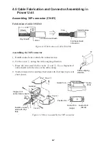
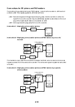
Assembling connector NCS-253P (CN-A15)
Armor
Vinyl sheath
Taping
Solder lead wire to armor and
connect it to #1 pin of connector.
#2
#3
#1
,,,,,,,,,,,,,
,,,,,,,,,,,,,
,,,,,,,,,,,,,
,,,,,,,,,,,,,
,,,,,,,,,,,,,
,,,,,,,,,,,,,
,,,,,,,,,,,,,
,,,,,,,,,,,,,
,,,,,,,,,,,,,
,,,,,,,,,,,,,
,,,,,,,,,,,,,
,,,,,,,,,,,,,
,,,,,,,,,,,,,
,,,,,,,,,,,,,
,,,
,,,
,,,
,,,
,,,
,,,
Conductor
S = 1.25 mm
∅
= 1.35 mm
2
Vinyl
sheath
Armor
Cable DPYCY-1.25
Use cable DPYCY-1.25
(Japan standard cable)
or equivalent cable.
Figure 4-7 Assembling connector NCS-253P
Summary of Contents for CSH-83
Page 1: ...COLOR SCANNING SONAR MODEL CSH 83 84 Back ...
Page 6: ...This page is intentionally left blank ...
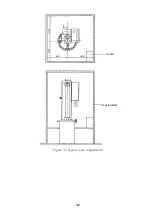
Page 11: ...3 2 Heater Heat insulator Figure 3 2 Typical sonar compartment ...
Page 68: ...A 10 ...
Page 77: ...A 19 ...
Page 78: ...A 20 ...
Page 79: ...A 21 ...
Page 80: ...A 22 ...
Page 81: ...A 23 ...
Page 82: ...A 24 ...
Page 83: ...A 25 ...
Page 84: ...A 26 ...
Page 85: ...D 1 ...
Page 86: ...D 2 ...
Page 87: ...Y Hatai D 3 ...
Page 88: ...D 4 ...
Page 89: ...Oct 31 03 D 5 ...
Page 90: ...Dec 10 02 D 6 ...
Page 91: ...D 7 ...
Page 92: ...D 8 ...
Page 93: ...D 9 ...
Page 94: ...D 10 ...
Page 95: ...D 11 ...
Page 96: ...D 12 ...
Page 97: ...D 13 ...
Page 98: ...D 14 ...
Page 99: ...D 15 ...
Page 100: ...D 16 ...
Page 101: ...D 17 ...
Page 102: ...D 18 ...
Page 103: ...D 19 ...
Page 104: ...D 20 ...

