4-3
4.3 Location of Connectors
RECEIVER UNIT
REMOTE
CONTROL BOX
10S1259
(Max. 20 m)
10S1261 (Max. 5 m)
10S1260 (Max. 40 m)
10S1259 (Max. 20 m)
*3
DPYCY-4
*2
10S1258-1
(Max. 20 m)
10S1260 (Max. 20 m)
*1
10S1258-1
10S1258-1
(Max. 20 m)
10S1277, 7 m
*3 DPYCY-1.5
Notes:
Q
Figures in centimeters are the
cable lengths required inside the
units, including lengths for cable
fabrication.
Q
(*1) + (*2)
< 100m, (*2)<
20 m
Q
*3: These are Japan standard cables.
Use equivalent cables.
Q
*4: For blackbox type, the processor
unit is provided instead of the
display unit.
*4
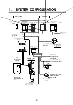
Figure 4-3 Location of connectors
Summary of Contents for CSH-83
Page 1: ...COLOR SCANNING SONAR MODEL CSH 83 84 Back ...
Page 6: ...This page is intentionally left blank ...
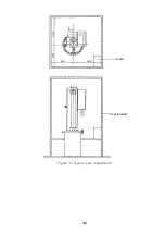
Page 11: ...3 2 Heater Heat insulator Figure 3 2 Typical sonar compartment ...
Page 68: ...A 10 ...
Page 77: ...A 19 ...
Page 78: ...A 20 ...
Page 79: ...A 21 ...
Page 80: ...A 22 ...
Page 81: ...A 23 ...
Page 82: ...A 24 ...
Page 83: ...A 25 ...
Page 84: ...A 26 ...
Page 85: ...D 1 ...
Page 86: ...D 2 ...
Page 87: ...Y Hatai D 3 ...
Page 88: ...D 4 ...
Page 89: ...Oct 31 03 D 5 ...
Page 90: ...Dec 10 02 D 6 ...
Page 91: ...D 7 ...
Page 92: ...D 8 ...
Page 93: ...D 9 ...
Page 94: ...D 10 ...
Page 95: ...D 11 ...
Page 96: ...D 12 ...
Page 97: ...D 13 ...
Page 98: ...D 14 ...
Page 99: ...D 15 ...
Page 100: ...D 16 ...
Page 101: ...D 17 ...
Page 102: ...D 18 ...
Page 103: ...D 19 ...
Page 104: ...D 20 ...

