8-2
1
1
TB-E1
TB-B1
CN-E1
2
2
3
4
5
3
2
1
6
7
8
9
10
11
P
P
12
13
14
15
16
RED
RED
BLK
WHT
BRN
BLK
RED
BLK
WHT
BRN
BLK
2
BLK
3
WHT
4
5
BRN
6
BLK
Transmitter Unit
CSH-810
Power Unit
CSH-880
Current Limiter Box CSH-1400
TR Inverter
TR-24100
P
P
*DPYCY-3.5
*DPYCY-3.5
*DPYCY-5.5
24 VDC
Ship s mains
10S1259
10S1259
*DPYCY-3.5
1
RED
2
BLK
3
TB-01
WHT
4
5
BRN
6
BLK
P
1
RED
2
BLK
3
TB-02
WHT
4
5
BRN
6
BLK
100 VAC
OUTPUT
-
+
INPUT
24 VDC
Inverter
TR-2435
100 VAC
OUTPUT
-
+
INPUT
24 VDC
CN-A15
Display Unit
CSH-
8
30
CSH-
8
400
*: Local supply
1 kVA
350 VA
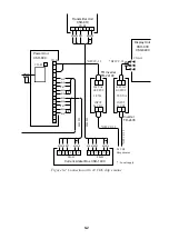
Figure 8-2 Connection with 24 VDC ship’s mains
Summary of Contents for CSH-83
Page 1: ...COLOR SCANNING SONAR MODEL CSH 83 84 Back ...
Page 6: ...This page is intentionally left blank ...
Page 11: ...3 2 Heater Heat insulator Figure 3 2 Typical sonar compartment ...
Page 68: ...A 10 ...
Page 77: ...A 19 ...
Page 78: ...A 20 ...
Page 79: ...A 21 ...
Page 80: ...A 22 ...
Page 81: ...A 23 ...
Page 82: ...A 24 ...
Page 83: ...A 25 ...
Page 84: ...A 26 ...
Page 85: ...D 1 ...
Page 86: ...D 2 ...
Page 87: ...Y Hatai D 3 ...
Page 88: ...D 4 ...
Page 89: ...Oct 31 03 D 5 ...
Page 90: ...Dec 10 02 D 6 ...
Page 91: ...D 7 ...
Page 92: ...D 8 ...
Page 93: ...D 9 ...
Page 94: ...D 10 ...
Page 95: ...D 11 ...
Page 96: ...D 12 ...
Page 97: ...D 13 ...
Page 98: ...D 14 ...
Page 99: ...D 15 ...
Page 100: ...D 16 ...
Page 101: ...D 17 ...
Page 102: ...D 18 ...
Page 103: ...D 19 ...
Page 104: ...D 20 ...

