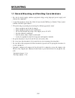
1-11
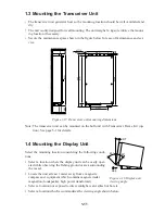
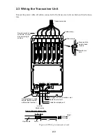
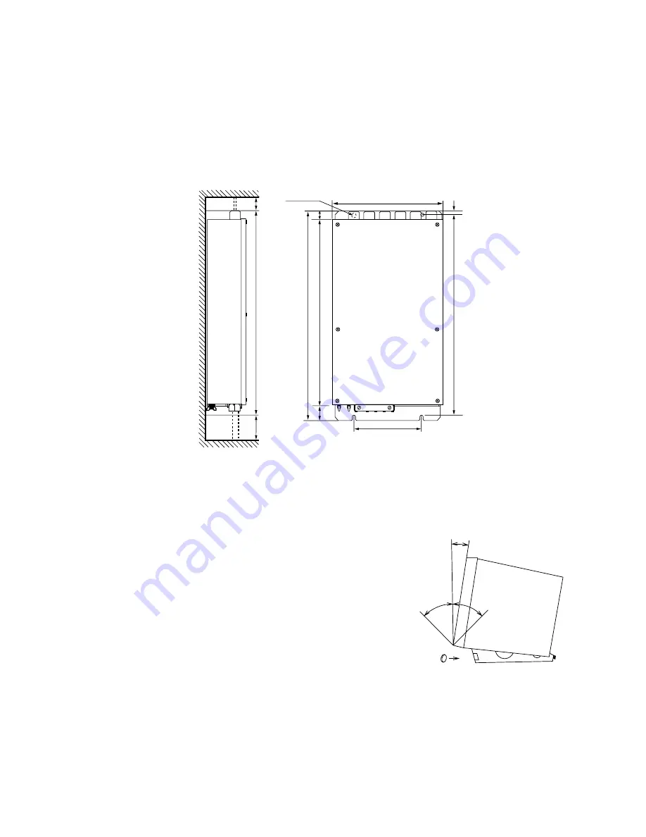
1.3 Mounting the Transceiver Unit
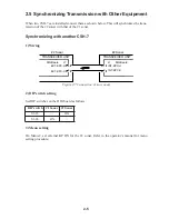
• The transceiver unit generates heat so the mounting location should be well ventilated and
dry.
• The unit is only designed for wall mounting. The unit weighs 14 kg so reinforce the mount-
ing location if necessary.
• Secure the maintenance space shown in the figure below for ease of maintenance and ser-
vice.
340
(645)
#100
645
#100
4-
∅
10
13
620
±
1
210
±
1
27
48
(570)
Fixing hole
Figure 1-17 Transceiver unit mounting dimensions
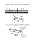
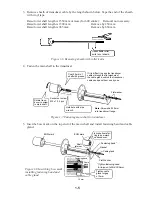
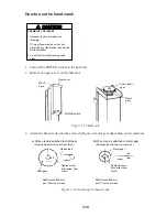
Note: The transceiver unit can be mounted on the hull unit with Transceiver Frame Kit (op-
tion). See page 5-1 for details.
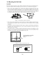
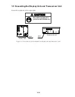
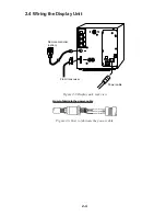
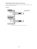
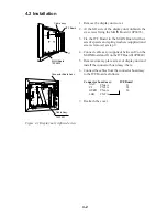
1.4 Mounting the Display Unit
Select the mounting location considering the following condi-
tions:
• Select a location where the display unit can be easily oper-
ated while observing the fishing ground or area surrounding
the vessel.
• Locate the unit at least 1 meter away from a magnetic
compass and equipment which contains magnets (radar
magnetron, loudspeaker, high power transformer).
• Select a location not exposed to direct sunlight, water splash or hot air.
• Select a location which accommodates the viewing angle shown below.
Cap
CRT
45°
45°
Figure 1-18 Display unit
viewing angle
Summary of Contents for CSH-7
Page 1: ...COLOR SCANNING SONAR MODEL CSH 7 ...
Page 4: ...ii ...
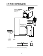
Page 6: ...iv SYSTEM CONFIGURATION ...
Page 15: ...1 8 ...
Page 16: ...1 9 ...
Page 35: ......
Page 36: ......
Page 37: ......
Page 38: ......
Page 39: ......
Page 40: ......
Page 41: ......
Page 42: ......
Page 43: ......
Page 44: ......
Page 45: ......
Page 46: ......
Page 47: ......
Page 48: ......
Page 49: ......
Page 50: ......
Page 51: ......
Page 52: ......
Page 53: ......
Page 54: ......
Page 55: ......
Page 56: ......
Page 57: ......
Page 58: ......


