1-4
Assembly and installation of the hull unit
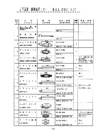
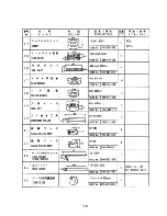
The hull unit is shipped disassembled as the parts shown on pages 1-8 and 1-9. Assemble the
hull unit as follows:
Necessary tools
t
r
a
P
e
z
i
S
s
k
r
a
m
e
R
h
c
n
e
r
W
)
m
m
7
1
e
z
i
s
x
e
H
(
0
1
M
r
o
F
.
d
e
d
n
e
m
m
o
c
e
r
s
i
h
c
n
e
r
w
d
n
e
-
e
l
b
u
o
D
h
c
n
e
r
W
)
m
m
0
3
e
z
i
s
x
e
H
(
0
2
M
r
o
F
d
n
a
l
g
e
l
b
a
c
g
n
i
n
e
t
s
a
f
r
o
F
h
c
n
e
r
W
e
p
i
P
m
m
5
5
e
g
n
a
l
f
y
d
o
b
n
i
a
m
g
n
i
x
i
f
r
o
F
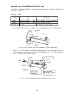
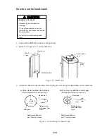
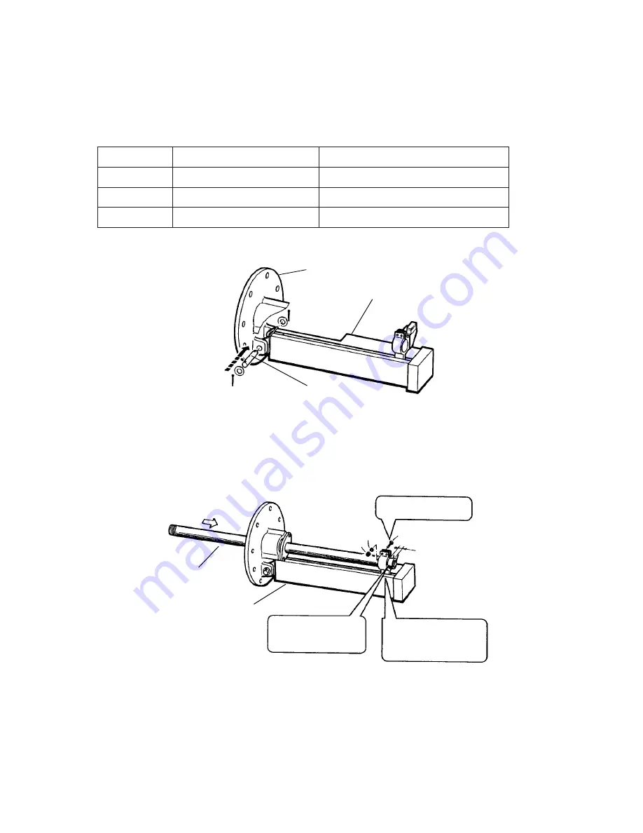
1. Fasten the raise/lower drive assembly to the main body flange with the trunnion shaft.
Split pin
Trunnion
shaft
Main body
flange
Raise/lower
drive assy.
Flat washer
Flat washer
Figure 1-4 How to fasten raise/lower drive assy. to main body flange
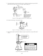
2. Coat the top of the main shaft with a small amount of grease. Pass the main shaft through the
main body flange, and fix it temporarily with the shaft retainer. (The shaft retainer should be
secure enough to prevent shaft rotation.)
Main shaft
Raise/lower
drive assy.
Wipe off grease
before tightening
shaft retainer.
Main shaft should
protrude by 15 mm from
top of shaft retainer.
Grease threads.
M10
M10 Spring washer
M 10 x 35
15 mm
Figure 1-5 Passing main shaft through the raise/lower drive assy.
Summary of Contents for CSH-7
Page 1: ...COLOR SCANNING SONAR MODEL CSH 7 ...
Page 4: ...ii ...
Page 6: ...iv SYSTEM CONFIGURATION ...
Page 15: ...1 8 ...
Page 16: ...1 9 ...
Page 35: ......
Page 36: ......
Page 37: ......
Page 38: ......
Page 39: ......
Page 40: ......
Page 41: ......
Page 42: ......
Page 43: ......
Page 44: ......
Page 45: ......
Page 46: ......
Page 47: ......
Page 48: ......
Page 49: ......
Page 50: ......
Page 51: ......
Page 52: ......
Page 53: ......
Page 54: ......
Page 55: ......
Page 56: ......
Page 57: ......
Page 58: ......


