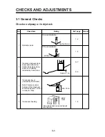
2-2
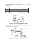
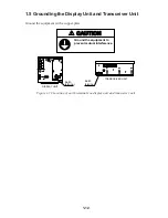
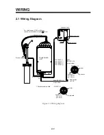
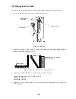
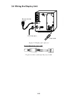
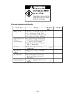
2.2 Wiring the Hull Unit
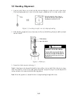
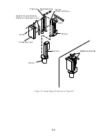
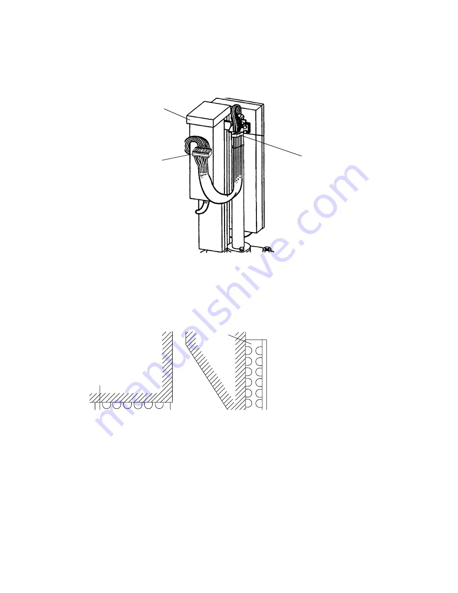
Transducer cables should not be stretched unduly during raising or lowering operation.
1. Fix six cables from raise/lower assy. with cable clamp
Å
.
Cable clamp
Å
Raise/lower
drive assy.
Cable calmp
ı
Figure 2-2 Hull unit
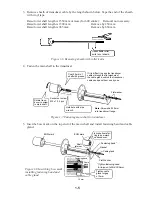
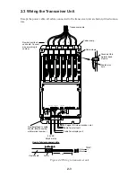
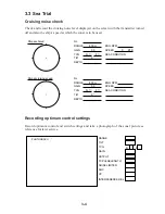
2. Run the six cables to cable clamp
ı
on the raise/lower assy. and position them as shown
below. Temporarily tighten clamp
ı
.
a b
c
d
e
f
a
b
c
d
e
f
Cable clamp
ı
Cable
clamp
Å
Example: Wire
a
of clamp
Å
to
a
of clamp
ı
.
Figure 2-3 Cable clamps and positioning of cables
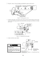
3. Adjust the cable lengths between cable clamps a and b as follows:
Cable length between
a
of
Å
and
a
of
ı
:
600 stroke: 660 mm
400 stroke: 580 mm
4. Adjust slack of five other cables so it is the same as the ones adjusted at step 3. Tighten the
cable clamp
ı
.
Summary of Contents for CSH-7
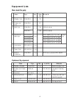
Page 1: ...COLOR SCANNING SONAR MODEL CSH 7 ...
Page 4: ...ii ...
Page 6: ...iv SYSTEM CONFIGURATION ...
Page 15: ...1 8 ...
Page 16: ...1 9 ...
Page 35: ......
Page 36: ......
Page 37: ......
Page 38: ......
Page 39: ......
Page 40: ......
Page 41: ......
Page 42: ......
Page 43: ......
Page 44: ......
Page 45: ......
Page 46: ......
Page 47: ......
Page 48: ......
Page 49: ......
Page 50: ......
Page 51: ......
Page 52: ......
Page 53: ......
Page 54: ......
Page 55: ......
Page 56: ......
Page 57: ......
Page 58: ......