

1-6
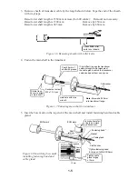
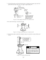
6. Set grease cotton to main body flange and tighten the grease cotton retainer.
Wind grease cotton
onto main shaft and
cut as below.
Space joints of cotton at 120
°
and push into
main body flange.
Tighten grease
cotton retainer for
gap of 7 to 9 mm.
Flat washer
Figure 1-9 Setting grease cotton
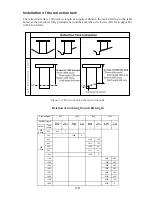
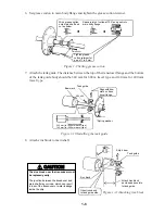
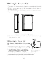
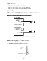
7. Attach the tank guide. The distance between the top of the transducer flange and the bottom
of the tank guide body should be 340 mm for 600 m travel type and 140 mm for 400 mm
travel type.
Bow mark
Tank guide
Align with bow
mark on trans-
ducer flange.
340 mm (for 600 mm travel type)
140 mm (for 400 mm travel type)
M10 x 55
M10 SW*
* Spring washer
Figure 1-10 Installing the tank guide
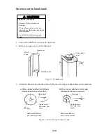
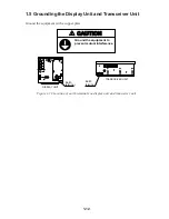
8. Attach zinc block to main shaft..
CAUTION
The zinc block near the transducer must
be replaced yearly.
The junction between the transducer and
main shaft may corrode, which can result
in loss of the transducer or water leakage
inside the ship.
Ship's bow
Tank guide
Zinc block
Orient round end
to tank guide side.
Attach zinc block
as close as possible
to tank guide.
Figure 1-11 Attaching zinc block
Summary of Contents for CSH-7
Page 1: ...COLOR SCANNING SONAR MODEL CSH 7 ...
Page 4: ...ii ...
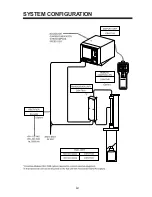
Page 6: ...iv SYSTEM CONFIGURATION ...
Page 15: ...1 8 ...
Page 16: ...1 9 ...
Page 35: ......
Page 36: ......
Page 37: ......
Page 38: ......
Page 39: ......
Page 40: ......
Page 41: ......
Page 42: ......
Page 43: ......
Page 44: ......
Page 45: ......
Page 46: ......
Page 47: ......
Page 48: ......
Page 49: ......
Page 50: ......
Page 51: ......
Page 52: ......
Page 53: ......
Page 54: ......
Page 55: ......
Page 56: ......
Page 57: ......
Page 58: ......