Data Format
3-4
C141-E198
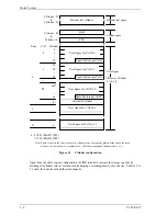
A number starting with 0 is assigned to each cylinder required in the user space in ascending order.
If the number of cylinders do not reach the maximum, the rest of the cylinders will not be used.
Always one cylinder that is located at the end of each zone in the user space can be established as an
alternate cylinder. Alternate cylinders will be used for alternate blocks when primary cylinders in the
user space are used up. See Subsections 3.1.2 and 3.3.2 for details.
(2)
Internal test space
The Internal test space is an area for diagnostic purposes only and its data block length is always
512KByte. The Internal test space consists of 8 cylinders and outer-host cylinder is always assigned.
The user cannot change the number of cylinders in the Internal test space or their positions.
(3) System
space
The system space is an area for exclusive use of the IDD itself and the following information are
recorded.
•
Defect list (P list and G list)
•
MODE SELECT parameter (saved value)
•
Statistical information (log data)
•
Controller control information
The above information is duplicated in several different locations for safety.
Note:
The system space is also called SA space.
3.1.2
Alternate spare area
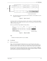
The alternate spare area consists of the last track of each cell in the user space and an alternate
cylinder allocated to the last cylinder of each zone.
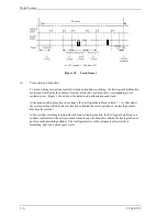
The spare area in each cell is placed at the end of the last track as shown in Figure 3.2. These spare
sectors are located in the end of the track logically, not necessarily located at the end physically
because of track skew or cylinder skew. (Details are explained on Subsection 3.1.3.)
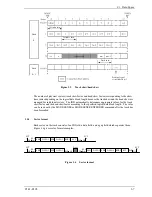
Size can be specified by the MODE SELECT command.
The number of spare sectors per cell can be specified from 0 to 168. The default for the spare sectors
number is 168.
Summary of Contents for MAS3367FC
Page 1: ...C141 E198 02EN MAS3735FC MAS3367FC DISK DRIVES PRODUCT MAINTENANCE MANUAL ...
Page 4: ...This page is intentionally left blank ...
Page 8: ...This page is intentionally left blank ...
Page 12: ...This page is intentionally left blank ...
Page 20: ...This page is intentionally left blank ...
Page 36: ...This page is intentionally left blank ...
Page 52: ...This page is intentionally left blank ...
Page 62: ...Installation Requirements 4 10 C141 E198 Figure 4 10 SCA2 type connector ...
Page 108: ...This page is intentionally left blank ...
Page 110: ...This page is intentionally left blank ...
Page 112: ...This page is intentionally left blank ...
Page 113: ......
Page 114: ......


