Data Format
3-10
C141-E198
(1)
Block address of user space
The logical data block address number is consecutively assigned to all of the data blocks in the user
space starting with 0 to the first data block.
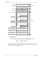
The IDD treats sector 0, track 0, cylinder 0 as the first logical data block. The data block is allocated
in ascending order of addresses in the following sequence (refer to Figure 3.5):
1) Logical data blocks are assigned in ascending order of sector number in the same track.
2) Subsequent logical data blocks are assigned to sectors in every track except the last track in
ascending order of track number in the same track (head). Within the same track, logical data
blocks are assigned in the same way as step 1).
3) Subsequent logical data blocks are assigned to sectors in every track except the last track in
ascending order of track number in the same cell. Within the same track, logical data blocks are
assigned in the same way as step 1).
4) For the last track in the same cell, subsequent logical data blocks are assigned to sectors other
than spare sectors in ascending order of sector number.
5) After blocks have been assigned in the same cell according to steps 1) to 4), subsequent logical
data blocks are assigned in ascending order of cell number in the same way as in steps 1) to 4).
Logical data blocks are assigned starting from track 0 in the next cell until the last cylinder
(immediately preceding the alternate cylinder n-1 shown in Figure 3.1) of the zone except
alternate cylinders in cells in the user space.
When the logical data block is allocated, some sectors (track skew and head skew) shown in Figure
3.5 are provided to avoid waiting for one turn involving head and cylinder switching at the location
where the track or the head is physically switched.
See Subsection 3.3.2 for defective/alternate block treatment and the logical data block allocation
method in case of defective sectors exist on the disk.
(2) Alternate
area
Alternate areas in the user space (spare sectors in the cell and alternate cylinders) are not included in
the above logical data block addresses. Access to sectors which are allocated as an alternate block in
the alternate area is made automatically by means of IDD sector slip treatment or alternate block
treatment (explained in Subsection 3.3.2), so the user does not have to worry about accessing the
alternate area. The user cannot access with specifying the data block on the alternate area explicitly.
Summary of Contents for MAS3367FC
Page 1: ...C141 E198 02EN MAS3735FC MAS3367FC DISK DRIVES PRODUCT MAINTENANCE MANUAL ...
Page 4: ...This page is intentionally left blank ...
Page 8: ...This page is intentionally left blank ...
Page 12: ...This page is intentionally left blank ...
Page 20: ...This page is intentionally left blank ...
Page 36: ...This page is intentionally left blank ...
Page 52: ...This page is intentionally left blank ...
Page 62: ...Installation Requirements 4 10 C141 E198 Figure 4 10 SCA2 type connector ...
Page 108: ...This page is intentionally left blank ...
Page 110: ...This page is intentionally left blank ...
Page 112: ...This page is intentionally left blank ...
Page 113: ......
Page 114: ......


