


5.
Monitor
Application
Copyright© 2009-2017 Fujitsu General Limited. All rights reserved.
63
Screen
Function
Par.
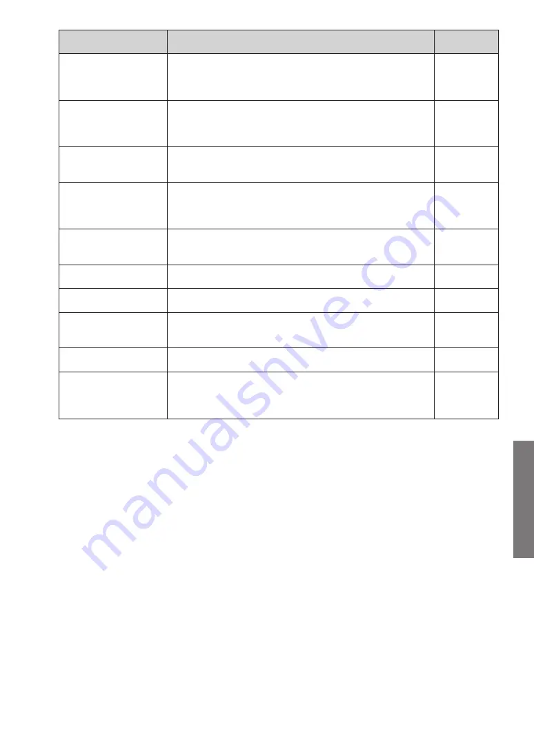
System List screen
Lists the status of each unit and the overall operating status
can be grasped. This screen is displayed when shifting from
the menu screen.
par. (-3
Detail Diagram screen
Performs normal operation check and cause specification
when an error was occurred from the detailed status display
of the units.
par. (-(
Detail Status List
screen
Detail data for all the units in the specified refrigerant circuit
will be displayed at a certain point of time.
par. (-(
Detail Check List
screen
Calculates each check item by the value of sensor inside the
outdoor unit or indoor unit and judges whether the results are
normal or not.
par. (-6
Operation History
screen
Displays the indoor units or outdoor units operating history
information for each unit.
par. (-7
Error History screen
Displays the error information for each unit.
par. (-8
Graph screen
Displays the sensor information by more detailed graph.
par. (-9
Operation Setting
screen
Operation of each refrigerant circuit, indoor unit, or R.C. group
can be controlled.
par. (-12
Data Backup screen
Any unit data currently displayed can be saved.
par. (-11
Setting
Data Recording Setting and Room Temperature Display
Selection can be operated and VRF Sensor Mark List and
Troubleshooting can be checked.
par. (-13
Summary of Contents for AIRSTAGE UTY-ASGXZ1
Page 2: ......


