Instruction Manual
Fuji Electric Co.,Ltd.
INZ-TN1ZRFb-E
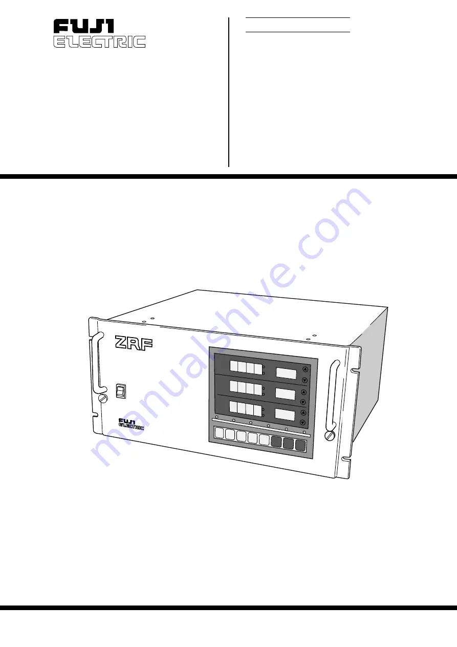
NON-DISPERSION TYPE
INFRARED GAS ANALYZER
TYPE: ZRF
INFRARED GAS AN
ALYZER
NO
vol%
ppm
vol%
ppm
RANGE
RANGE
AUTO CAL
HOLD
SPAN
CAL
SPAN
ZERO
ENT
COMP
FUNC
∧
>
MEAS
MEAS
RMT RANGE
SO
2
vol%
ppm
RANGE
O
2
POWER
ON
OFF


