PRIVATE AND CONFIDENTIAL © 2020 FRTEK CO., LTD.
1
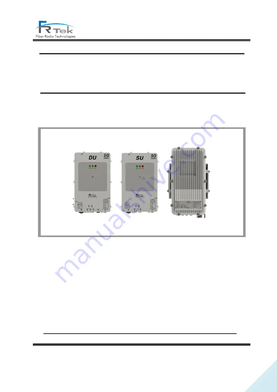
PrimAer 28
Operating Manual
PrimAer 28GHz
Operating Manual
Document Reference
Company:
Fiber Radio Technologies
Version:
Ver 0
Document Status:
Release 1
Issue Date:
2020. 11.
Department:
R&D Group 1
Author Manager:
Jun Sung, Park


