


32
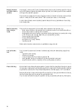
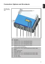
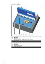
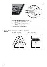
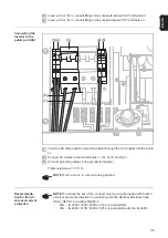
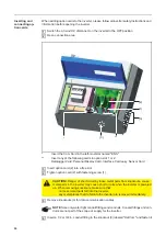
AC-side terminals
and grounding
terminals
The white plastic divider that separates the AC from the DC connection area is not shown
in the figure.
(1)
Grid grounding / Grounding conductor
The inverter must be connected via the grounding terminal to the AC grid ground-
ing.
NOTE!
-
Use copper wires for all grounding cables.
-
Use only solid or stranded wire. Do not use fine stranded wire.
-
See NEC section 250 for correct grounding.
(2)
= Neutral conductor N
NOTE!
The neutral conductor is not bonded to ground internally.
(3)
AC disconnect
(4)
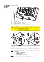
Grounding of photovoltaic components (e.g., solar module frames)
The ground for photovoltaic components such as solar module frames must be
connected at the grounding terminals. The size of the wire usually corresponds to
the largest wire in the DC system.
(5)
Grounding Electrode Terminal (GET)
A grounding electrode terminal may be required depending on local regulations
(6)
(7)
(4)(5)
(1)(2)
(3)
N
Summary of Contents for IG 2000
Page 2: ...0...
Page 4: ...2...
Page 6: ...4...
Page 10: ...8...
Page 15: ...General Information...
Page 16: ......
Page 21: ...Installation and Startup...
Page 22: ......
Page 50: ...48...
Page 51: ...Operation...
Page 52: ......
Page 80: ...78...
Page 81: ...Troubleshooting and Maintenance...
Page 82: ......
Page 95: ...Appendix...
Page 96: ......
Page 113: ...111 EN US...
Page 114: ...112...
Page 115: ...113 EN US...


