background image

Installation and Operating Instructions

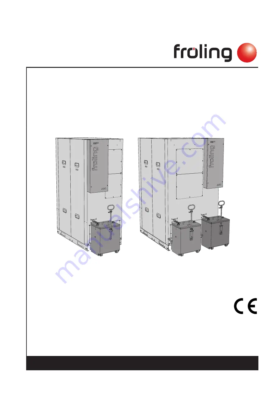
Modular electrostatic precipitator system EF 250-500


EF 250

EF 500

Translation of the original German operating and installation instructions for technicians and operators

Read and follow the instructions and safety information!

Technical changes, typographical errors and omissions reserved!

M2140120_en | Edition 08/09/2020

Fröling GesmbH | A-4710 Grieskirchen, Industriestraße 12 | www.froeling.com

Summary of Contents for EF 250

Page 1: ...ion of the original German operating and installation instructions for technicians and operators Read and follow the instructions and safety information Technical changes typographical errors and omissions reserved M2140120_en Edition 08 09 2020 Fröling GesmbH A 4710 Grieskirchen Industriestraße 12 www froeling com ...

Page 2: ...ipitator system from the pallet 16 5 4 2 Recommended clearances in the boiler room 17 5 5 Adjusting the height of the ash container 18 5 6 Adapting the handle on the ash container 18 5 7 Fitting the flue gas temperature sensor 19 5 8 Adapting the electrostatic precipitator system if required 20 5 8 1 Modification of the ash container on the opposite side of the filter system 21 Removing the ash co...

Page 3: ...5 7 1 Checking the fill level of the ash container and emptying if required 37 8 Periodic inspection and cleaning 38 8 1 Cleaning electrodes and the interior 38 9 Decommissioning 40 9 1 Disassembly 40 9 2 Disposal 40 10 Notes 41 11 Appendix 44 11 1 Addresses 44 11 1 1 Address of manufacturer 44 Customer service 44 11 1 2 Address of the installer 44 Table of contents Installation and Operating Inst...

Page 4: ...ow doku froeling com Subject to technical change 1 1 Operating principle The modular electrostatic precipitator system operates on the electrostatic principle of corona discharge The flue gas from the boiler flows together with the fine dust particles 1 produced during combustion into the electrostatic precipitator system where electrons 3 are released from the high voltage electrodes 2 which elec...

Page 5: ...t follow the instructions WARNING The dangerous situation may occur and if measures are not observed it will lead to serious injury or death Work with extreme care CAUTION The dangerous situation may occur and if measures are not observed it will lead to minor injuries NOTICE The dangerous situation may occur and if measures are not observed it will lead to damage to property or pollution Safety 2...

Page 6: ...procedures These stickers must not be removed or covered Refer to the operating instructions Wear safety shoes Wear protective gloves Turn off the main switch Wear a dust mask Wear suitable protective clothing Unauthorised access prohibited Prohibited for persons with pacemakers Warning hot surface Warning hazardous electrical voltage Warning hazardous or irritant materials Hand injury warning War...

Page 7: ...th the following Froling heating systems Electrostatic precipitator system EF 250 Turbomat TM 150 250 Electrostatic precipitator system EF 500 Turbomat TM 320 Turbomat TM 400 500 The electrostatic precipitator system is integrated between the boiler and the flue gas system with the boiler induced draught needing to be connected to the precipitator outlet Use only the fuels specified in the intende...

Page 8: ...installation by unqualified persons Risk of personal injury and damage to property During assembly and installation Observe the instructions and information in the manuals Only allow appropriately qualified personnel to work on the system Assembly installation initial startup and servicing must always be carried out by qualified personnel Heating technician building technician Electrical installat...

Page 9: ... When working with dust from the electrostatic particle separator use dust masks in filter class FFP2 or higher 2 6 Chimney connection chimney system The entire flue gas system must be designed to prevent wherever possible damage caused by seepage and insufficient feed pressure Raw gas temperatures below 65 C are not permitted in order to avoid condensation The chimney connection should be as shor...

Page 10: ...eter of the measuring probe used by Froling customer service is 14 mm To avoid measuring errors due to the ingress of false air the diameter of the measuring port must not exceed 21 mm 2 7 Residual risks DANGER If maintenance work is performed when the system is in operation Risk to life from high voltage electrodes Before carrying out work on in the electrostatic precipitator Switch off the power...

Page 11: ...trol signal of the boiler Before working on in the electrostatic precipitator system Shut down the boiler according to procedure Switch off the power supply to the boiler and take precautions to prevent accidental switching on Always have work carried out by a qualified electrician Work must not be carried out on electrical components by unauthorised persons DANGER Persons with pacemakers in the i...

Page 12: ...000 metres above sea level you should consult the manufacturer Danger of fire due to flammable materials The floor of the system must not be flammable No flammable materials should be stored near the system Flammable objects e g clothing must not be put on the system to dry Damage due to impurities in combustion air Do not use any solvents or cleaning agents containing chlorine and hydrogen halide...

Page 13: ...cipitator system 730 1070 L Total length incl fittings 1873 L1 Length without container 1589 L2 Length of electrostatic precipitator system 1275 H Height of electrostatic precipitator system 1950 H1 Height of clean gas outlet connection 1578 H2 Height of raw gas inlet connection 1178 D Flue spigot diameter outside 180 350 EF 250 EF 500 Technical information 4 Dimensions Installation and Operating ...

Page 14: ...lectrode voltage V 30 000 Max permitted boiler flue gas temperature C 200 Minimum filter inlet temperature C 90 Minimum filter outlet temperature C 65 Maximum ambient temperature in installation room C 35 Reduction of flue gas temperature in filter K 20 Max permitted nominal output kW 250 500 Max permitted flue gas mass flow g s 195 390 Max permitted flue gas flow rate m h 820 1645 Fluidic resista...

Page 15: ...nsport The product is delivered on pallet s NOTICE Possibility of damage to components if handled incorrectly Follow the transport instructions on the packaging Transport components with care to avoid damage Protect components against damp Pay attention to the pallet s centre of gravity when lifting 5 2 Temporary storage If the system is to be assembled at a later stage Store components at a prote...

Page 16: ... cover Hook the crane hook onto the crane eyelets and position the electrostatic precipitator system 5 4 Setting up in the boiler room 5 4 1 Removing the electrostatic precipitator system from the pallet Remove the transport locks and lift the electrostatic precipitator system from the pallet Place the electrostatic precipitator system in the desired location Observe the maintenance areas See Reco...

Page 17: ...Observe the applicable standards and regulations when setting up the system Observe additional standards for noise protection ÖNORM H 5190 Noise protection measures EF 250 EF 500 A B C A C B D Description A Ash container maintenance area 200 mm B Left maintenance area 400 mm C Geared motor maintenance area 200 mm D Right maintenance area 1 400 mm 1 Only for electrostatic precipitator system EF 500...

Page 18: ...ally with the adjustable foot 5 6 Adapting the handle on the ash container The ash container can be pulled or carried depending on the situation Remove the pipe locking pin on the ash container Insert the handle with carrying bar on the side of the ash container Push the second handle onto the carrying bar and secure it with the pipe locking pin 5 Assembly Adjusting the height of the ash container...

Page 19: ...wer flue pipe connection and secure with a wing screw Run the flue gas temperature sensor cable to the boiler controller and connect it according to the enclosed wiring diagram See Electrical connection page 32 Assembly 5 Fitting the flue gas temperature sensor Installation and Operating Instructions EF 250 500 M2140120_en 19 ...

Page 20: ...s in the lower area the clean gas outlet in the upper area These connections can be positioned according to the requirements and do not have to be arranged one above the other NOTICE If modification work is to be carried out it is recommended that the filter is not installed in the desired position until the work has been completed in order to have sufficient all round space The following modifica...

Page 21: ... detach the side panel Removing the ash container and fittings Remove the key plate from the safety switch Push the locking lever up to release the ash container Pull out the ash container Remove the cover plate Assembly 5 Adapting the electrostatic precipitator system if required Installation and Operating Instructions EF 250 500 M2140120_en 21 ...

Page 22: ...s sufficient Lay the cable in cable duct A Removing the drive and fittings Loosen the plug on the geared motor Loosen shaft retainer and remove geared motor Remove key from shaft groove Remove cover plate and small cover plate above Position the geared motor extension cable on the opposite side of the filter system laying the cable in the cable duct 5 Assembly Adapting the electrostatic precipitat...

Page 23: ...ve lever Remove the holding bracket of the proximity sensor Position the holding bracket with the proximity sensor on the opposite side of the filter system Pull out the cable of the proximity sensor from the control cabinet until the cable length is sufficient Lay the cable of the proximity sensor in the cable duct Loosen the screw connection and unthread the securing plate Assembly 5 Adapting th...

Page 24: ...mantled ash removal flange incl ash screw on the opposite side of the filter system Insert key into shaft groove Install the gear wheel incl drive linkage as shown Insert the securing plate into the groove of the drive linkage and secure it with screws 5 Assembly Adapting the electrostatic precipitator system if required 24 Fröling GesmbH A 4710 Grieskirchen Industriestraße 12 www froeling com ...

Page 25: ...te of the filter The rubber buffer must point towards the stop lever Mount the clamping lever on the clamping bracket Attach the tension spring to the tension lever and to the stop lever and press downwards Attach to the previously used hole A Secure the position of the clamping lever with eyebolt and spring cotter Assembly 5 Adapting the electrostatic precipitator system if required Installation ...

Page 26: ...lide the geared motor onto the shaft and secure it with the shaft retainer Connect the extension cable to the geared motor Installing the ash container and fittings on opposite side Position safety limit switch behind insulation and secure with screws Install the ash removal flange Ensure correct positioning of the ash screw 5 Assembly Adapting the electrostatic precipitator system if required 26 ...

Page 27: ...n the opposite side NOTICE If the control cabinet remains at the front when the bypass flap drive is modified the cable of the drive must be extended Loosen the wing screw on the lower flue pipe connection and remove the temperature sensor Dismantle the cover plates on the flue pipe connections and remove the thermal insulation A Dismantle flue pipe flanges Assembly 5 Adapting the electrostatic pr...

Page 28: ...d remove the washers and silicone foam seal Remove covers Loosen the screw connections on the shafts and remove the driver Turn the shaft counterclockwise until the bypass flaps are closed Remove the flap plate from the shaft and pull out the shaft 5 Assembly Adapting the electrostatic precipitator system if required 28 Fröling GesmbH A 4710 Grieskirchen Industriestraße 12 www froeling com ...

Page 29: ...ep 2 NOTICE If the central connections B are used place both locking plates on the top step step 1 Assembling the covers Slide both washers and silicone foam seal onto the shaft and fix with retaining bracket Insert previously removed thermal insulation Position the shaft bypass flap to the left stop Push the drive of the bypass flap onto the shaft so that the direction of rotation left L is visib...

Page 30: ...e pipe cover plates If the flue pipe flange of the flue gas outlet is mounted centrally on the upper side Take out the perforations A on the flue pipe flange and remove the burrs using a half round file Fit the covers 5 Assembly Adapting the electrostatic precipitator system if required 30 Fröling GesmbH A 4710 Grieskirchen Industriestraße 12 www froeling com ...

Page 31: ... The electrostatic precipitator system is placed between the boiler and the induced draught The piping must be provided by the customer in compliance with the recommended distances and the installation plan The pipeline must be as short as possible and insulated with suitable thermal insulation Connections A Lower flue gas connection Raw gas inlet pipe from boiler B Upper flue gas connection Clean...

Page 32: ...be provided from the boiler to the control cabinet of the electrostatic precipitator system Power supply 400 V Power supply 24 V X2X link IMPORTANT Route the cables so that they do not touch any hot parts and there is no danger of tripping Note All information on the electrical connection can be found in the enclosed wiring diagram 5 10 2 Potential equalisation The potential equalisation must comp...

Page 33: ...ler control section System menu System configuration Heating circuits system Flue gas treatment Navigate to the menu Flue gas treatment and select the filter type E filter All values can be configured in the following menu System menu Heating circuits system Flue gas treatment Flue gas filter For other settings refer to the operating instructions for the boiler controller supplied Commissioning 6 ...

Page 34: ... the ash screw as follows Remove the key plate of the ash container from the safety limit switch and re insert it Ash screw rotates for a few seconds IMPORTANT Ash screw rotates in an anti clockwise direction 6 Commissioning Check the direction of rotation of the ash screw 34 Fröling GesmbH A 4710 Grieskirchen Industriestraße 12 www froeling com ...

Page 35: ... General visual inspection for damage and check seal Cleaning condition of the filter system Check electrical power supply Check HV electrodes and high voltage power supply NOTICE Maintenance and servicing work must only be carried out by Froling customer services or a partner approved by Fröling Heizkessel und Behälterbau GesmbH WARNING Incorrect inspection and cleaning Incorrect or insufficient ...

Page 36: ...ng and finishing inspection and cleaning work Before starting any inspection and cleaning work 1 Shut down the boiler according to procedure 2 Switch off the main switch on the control cabinet of the electrostatic precipitator system and secure it against being switched on again After inspection and cleaning work Check that all covers and caps are closed Switch the main switch on the control cabin...

Page 37: ... the lock upwards to release the ash container Pull out the ash container Close the opening at the rear with the sliding valve A and take the ash container to the emptying point Loosen the ashes of the ash duct with a screwdriver and remove with an ash vacuum NOTICE Dispose of the ash in accordance with national regulations NOTICE After installing the ash container and inserting the key plate into...

Page 38: ...prior to emissions measurement 8 1 Cleaning electrodes and the interior Carry out the following cleaning work on all modules of the electrostatic precipitator system Loosen screws and remove the top cover Loosen the upper screws and unhook the side panels Remove maintenance cover Loosen screws on the insulator and remove the high voltage cable IMPORTANT When fitting the maintenance covers use the ...

Page 39: ...n the electrode basket and complete interior of the electrostatic precipitator system with a brush and an ash vacuum IMPORTANT Use a dust mask filter class FFP2 or higher CAUTION Clean the baskets very carefully they must not be deformed Check all seals for damage and replace if necessary Periodic inspection and cleaning 8 Cleaning electrodes and the interior Installation and Operating Instruction...

Page 40: ...Disposal Ensure that they are disposed of in an environmentally friendly way in accordance with waste management regulations You can separate and clean recyclable materials and send them to a recycling centre 9 Decommissioning Disassembly 40 Fröling GesmbH A 4710 Grieskirchen Industriestraße 12 www froeling com ...

Page 41: ...10 Notes Notes 10 Installation and Operating Instructions EF 250 500 M2140120_en 41 ...

Page 42: ...10 Notes 42 Fröling GesmbH A 4710 Grieskirchen Industriestraße 12 www froeling com ...

Page 43: ...Notes 10 Installation and Operating Instructions EF 250 500 M2140120_en 43 ...

Page 44: ...AUSTRIA TEL 0043 0 7248 606 0 FAX 0043 0 7248 606 600 EMAIL info froeling com INTERNET www froeling com Customer service Austria 0043 0 7248 606 7000 Germany 0049 0 89 927 926 400 Worldwide 0043 0 7248 606 0 11 1 2 Address of the installer Stamp 11 Appendix Addresses 44 Fröling GesmbH A 4710 Grieskirchen Industriestraße 12 www froeling com ...

Reviews: