


17 | © Frio 2021 - Rev. 0.3 - Updated 3/2/2021
4.3
S
TEP
3:
L
OW
V
OLTAGE
C
ONNECTIONS
1.
Once the controller is mounted, you may remove the clear plastic enclosure cover and the white wiring cover.
Always ensure that the wiring cover is in place before energizing the controller.
2.
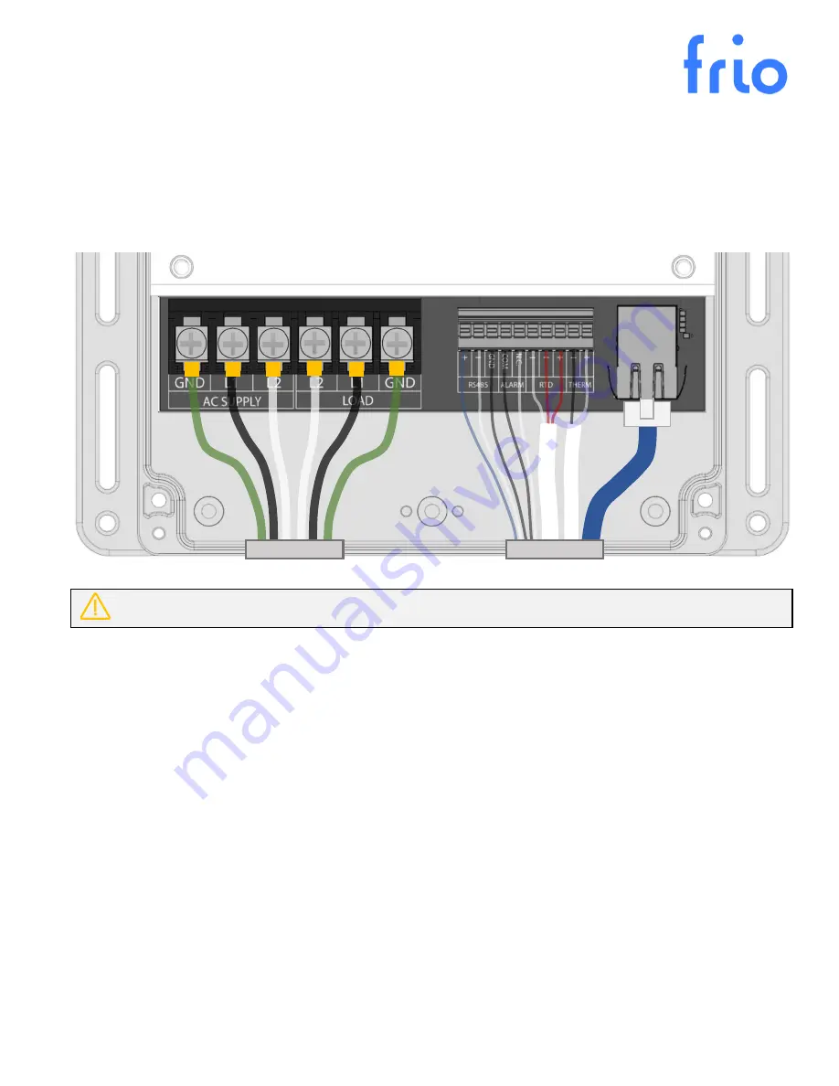
Connect low voltage sensor and communications wires according to the image in Figure 3.
3.
For more information on sensor compatibility and setup, please c
onsult the owner’s manual.
NOTE: THE SYSTEM SHOULD NEVER BE ENERGIZED WHEN THE WIRING COVER IS NOT IN PLACE.
4.4
S
TEP
4:
H
EAT
T
RACE AND
P
OWER
C
ONNECTION
1.
Ensure the circuit breaker that will power the controller is turned off.
2.
Use a Megger Test device to check the integrity of the heat trace in accordance with the heat trace
manufacturer’s instructions.
3.
Connect heat trace leads as shown in Figure 3. The ground sheath of the heat trace must be connected to the
ground terminal on the controller.
4.
Connect the power leads as shown in Figure 3. The ground connection on the controller must be properly
connected to ground in accordance with local and national electrical codes.
5.
All power connections and wires should be installed in accordance with all local and national electrical codes.
Use crimp connected spade terminals to ensure proper mounting in the power terminal blocks.
4.5
S
TEP
5:
S
TART
U
P AND
C
ONFIGURATION
1.
Close the wiring cover before energizing the system.
2.
Energize the system by turning on the circuit breaker for the heat tracing circuit.
3.
Press any button to access the
Main Menu
, then select
Settings
to configure the device. Refer to section 5.4 of
the S1 Operating Manual for available settings and consult section 3 to determine the control mode and
configuration that will best serve your purpose.
Figure 3: Top view of the Frio S1 controller with the wiring cover removed, showing all possible wiring connections.