


12 | © Frio 2021 - Rev. 0.3 - Updated 3/2/2021
3.4.4
Dry Contact
The Frio S1 is equipped with a dry contact to provide users with a low voltage alarm output option. The dry contact
is normally closed and opens when the Frio S1 has an alarm signal. The contacts are rated for 2 A maximum at 250
VAC and are compatible with 14-24 AWG wires. Users can set which alarms are enabled as described in the following
section. All enabled alarms will activate the dry contact.
3.5
A
LARMS
The Frio S1 may be configured to alarm under the various conditions described in this section. Alarms are divided into
two categories, critical (
High Current
,
Sensor Failure, and GFEP
) and non-critical (
Low Current
,
High Temperature
, and
Low Temperature
). The sensor failure and GFEP alarms are hard-coded and cannot be disabled. All other alarms are
user-settable and may be enabled or disabled via the HMI. All enabled alarms will activate the dry contact, and the
alarm LED. Critical alarms will either shut the system off or put the device into the failure state, which can be set by
the user via the HMI. Non-critical alarms will cause the alarm LED to light up and will activate the dry contact but will
not disrupt operation. Critical alarms are latching, meaning that if an alarm condition occurs, the alarm will be present
until the user resets the alarm from the HMI, even if the alarm condition is resolved. Non-critical alarms may be set
to be all latching or all non-latching. Non-latching alarms are dismissed when the alarm condition is resolved.
Online systems may be configured to notify users of alarm conditions through the Frio cloud platform. Users may also
use the cloud platform to view information about each alarm and, in some cases, to clear the alarm. Alarms on offline
systems can be viewed and resolved at the device via the HMI.
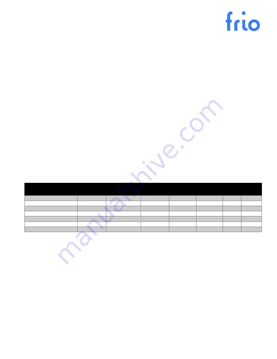
A summary of the available alarms is shown in the table below.
Alarm
Type
Critical
Default
Threshold
Range
Increment Delay
Default
Delay
Low Current
User-Settable
No
0 A
0-30 A
0.1 A
0-500 s
5 s
High Current
User-Settable
Yes (Shuts Off)
30 A
0-30 A
0.1 A
0-500 s
300 s
Low Temperature
User-Settable
No
35 °F
0-300 °F
1 °F
0-500 s
300 s
High Temperature
User-Settable
No
140 °F
64-300 °F
1 °F
0-500 s
300 s
Sensor Failure
Hard-coded
Yes (Failure State)
False
-
-
No
-
GFEP Trip
Hard-coded
Yes (Shuts Off)
30 mA
30-300 mA
5 mA
No
-
GFEP (Fire protection mode)
Hard-coded
Yes
30 mA
30-300 mA
5 mA
No
-
3.5.1
User-settable Alarms
User-settable alarms are designed to provide the user with a method to monitor their system and to understand if the
system is operating outside of normal bounds. These alarms may be enabled or disabled via the HMI and include
High
Current
,
Low Current
,
High Temperature
, and
Low Temperature.
Enabled alarms will activate the dry contact. With
the exception of high current, user settable alarms are not enabled by default and must be enabled by the user. To
configure user-settable alarms, select
Settings
from the
Main Menu
, then select
Advanced Settings
from the
Settings
Menu
. Select
Alarms
from the
Advanced Settings Menu
, then select the alarm you would like to adjust.
For each user-settable alarm, you will be able to: enable the alarm, set the threshold, and set the delay. The delay is
provided to reduce nuisance alarms. When using the high current alarm with self-regulating heat trace, it is highly
recommended to use a delay of at least 300s to avoid alarming due to inrush current when the heat trace is activated.
The high current alarm is a critical alarm and will shut off the system automatically if the alarm is enabled. It is also a
latching alarm and must be reset via the HMI. Non-critical user-settable alarms may be set to Latching or Non-latching
in the alarm settings. This setting will apply to all enabled non-critical alarms.