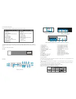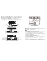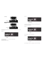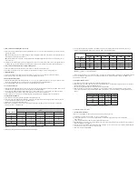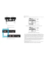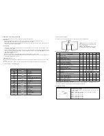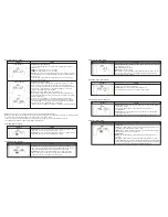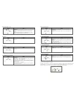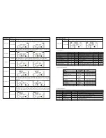
Operating mode/status
Description
LCD display
LCD display
When the input voltage is within an acceptable range, the UPS will provide pure and stable
AC power to the output. The UPS will also charge the battery in AC mode.
AC mode
ECO mode
CVCF mode
Battery mode
Bypass mode
Description
When the input voltage is within the voltage regulation range and ECO mode is enabled, the
UPS will bypass voltage to the output for energy saving.
Operating mode/status
Description
LCD display
When the input voltage is within an acceptable range, the UPS will provide pure and stable
AC power to the output. The UPS will also charge the battery in AC mode.
Fault status
LCD display
Description
When input frequency is within 46 and 64Hz, the UPS can be set at a constant output
frequency of 50Hz or 60Hz. The UPS will still charge the battery while operating in this mode.
LCD display
Description
When the input voltage exceeds the acceptable range or during a power failure, the UPS will
start supplying power from the battery while the alarm will beep every 4 seconds.
LCD display
Description
When the input voltage is within the acceptable range and the bypass is enabled, turn off the
UPS in order to transfer the unit to Bypass mode. The alarm beeps once every two minutes in
this case.
Battery test
LCD display
Description
When UPS is in AC mode or CVCF mode, press and hold the Test key for 0.5 second. The
UPS will beep once and start performing the “Battery test”. The line between I/P and inverter
icons blinks while the diagnostics is in progress. This operation is used to check the battery
status.
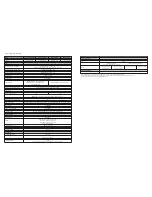
3-9. Fault codes
3-10. Warning indicators
Fault event
Bus start failure
Bus over
Bus under
Bus unbalanced
Inverter soft start failure
High inverter voltage
Low inverter voltage
Inverter output short circuited
Negative power fault
Inverter over current
Inverter waveform abnormal
Fault code
01
02
03
04
11
12
13
14
1A
60
63
Fault code
21
24
2a
31
36
41
42
43
6A
6B
6C
Fault event
Battery SCR short circuited
Inverter relay short circuited
Charger short circuited
Communication fault
Parallel output current unbalanced
Over temperature
CPU communication failure
Overload
Battery turn-on failure
PFC current failure in battery mode
Bus voltage changes too fast
Icon
None
None
None
None
None
None
None
None
None
None
Icon
None
None
None
None
None
None
None
None
None
None
3-11. Warning codes
Warning code
01
07
08
09
0A
0B
0D
0E
Warning code
10
21
22
33
3A
3D
3E
Warning event
Battery is not connected
Over charge
Low battery
Overload
Fan failure
EPO enable
Over temperature
Charger failure
Warning event
L1 IP fuse is blown
Line issues are different in a parallel system
Bypass issues are different in parallel system
Locked in bypass after an overload is detected 3 times in 30 minutes
Cover of maintenance switch is open
Bypass is unstable
Boot loader is missing
Warning
Battery low
Overload
Battery not connected
Over charge
EPO enable
Fan failure/Over temperature
Charger failure
I/P fuse broken
3 overload occurrences in 30min
Alarm
Beeps once every second
Beeps twice every second
Beeps once every second
Beeps once every second
Beeps once every second
Beeps once every second
Beeps once every second
Beeps once every second
Beeps once every second
Icon (blinking)
Summary of Contents for FDC-106KMR-ISO
Page 17: ......


