


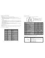
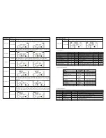


* CVCF stands for converter mode.
Mode
LED
UPS startup
Bypass mode
AC mode
Battery mode
CVCF mode
Battery test
ECO mode
Fault
Bypass
Line
Battery
Fault
Note: means LED is illuminated means LED is not illuminated
2-5. ForzaTracker monitoring software
ForzaTracker is a new generation of UPS monitoring software, which provides user-friendly interface to monitor and control your
Uninterruptible Power System. This unique software provides safe auto-shutdown for multi-computer systems during power
failures. With this software, users can monitor and control any UPS on the same LAN no matter how far they might be from the
UPS.
Installation procedure for Windows users:
1. Use the supplied CD or go to the website:
http://www.forzaups.com/us/driver-downloads/
.
2. After clicking the software icon, choose the required operation system.
3. Follow the on-screen instructions to install the software.
4. When you finished downloading all required files, enter the serial No (Installation Password):
5242-87f6-64re-di8d-986u
to install
the software (include the hyphens).
5. In order to access as Administrator, input the password: 111296.
6. When your computer restarts, the management software will appear as a light blue round icon located in the system tray, near
the clock.
For Mac users, please refer to the ForzaTracker quick installation guide inside the Mac folder.
3. Advanced operation
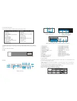
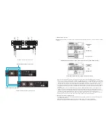
3-1. Description of buttons and functions
3-2. LED Indicators and LCD panel
There are four LEDs on front panel design to show the operation status of the UPS:
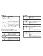
Function
Button
ON/Enter
Button
OFF/ESC
Button
Test/Up
Button
Mute/Down
Button
Test/Up +
Mute/Down
Button
Turns on the UPS
: Press and hold this button over 0.5 second to turn on the UPS.
Enter Key
: Press this button to confirm the selected settings of the configuration menu.
Turns off the UPS
: Press and hold this button for 0.5 second to turn off the UPS.
Esc key
: Press this button to return to the last setting of the configuration menu.
Battery test
: Press and hold this button for 0.5 second to test the battery status while
in AC mode, or CVCF mode.
UP key
: Press this button to display the next selection in the configuration menu.
Mutes the alarm:
Press and hold the button for 0.5 second to mute the buzzer.
Please refer to sections below for details.
Down key
: Press this button to display previous selection in the configuration menu.
Press and hold these two buttons simultaneously for 1 second either to enter
or exit the menu settings.
•
•
•
•
•
•
•
•
•
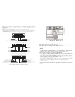
LCD Panel
BYPASS
LINE
BATTERY
FAULT
OFF/ESC
TEST/UP
MUTE/DOWN
ON/ENTER
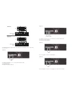
Backup
Time Info
Mode Operation
Info
Programmable
Output Info
Input & Battery
Voltage Info
Output & Battery
Voltage Info
Battery Info
Load Info
Fault
Info
Mute Operation
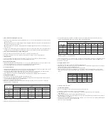
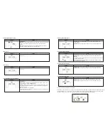
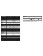
Display
Function
Backup time information
Fault information
Mute operation
Output & battery voltage information
Load information
Provides a digital indication of the battery discharge time.
H: hours, M: minutes, S: seconds
Indicates that a warning or fault has occurred.
Displays the fault codes, listed in detail in the sections below.
Indicates that the UPS alarm has been disabled.
Provides an indication of the output voltage, frequency or battery
voltage. VAC: output voltage, VDC: battery voltage, Hz: frequency
Indicates the load level at 0-25%, 26-50%, 51-75%, and 76-100%
Overload indication.
Indicates the load or the output is short-circuited.
Display
Function
Backup time information
Fault information
Mute operation
Output & battery voltage information
Provides a digital indication of the battery discharge time.
H: hours, M: minutes, S: seconds
Indicates that a warning or fault has occurred.
Displays the fault codes, listed in detail in the sections below.
Indicates that the UPS alarm has been disabled.
Summary of Contents for FDC-106KMR-ISO
Page 17: ......


