


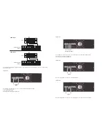


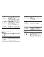
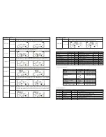


Parameter 3:
000~999:
Sets the maximum backup time from 0min to 999min. UPS will shut
down to protect battery after backup time expires. The default value is
990min.
DIS:
When battery discharge protection is disabled, the backup time will
depend on battery capacity. “
DIS
” is the default value.
Interface
Setting
09: Battery backup time setting
Reserved
Interface
Setting
10: Reserved
Reserved
Interface
Setting
11: Reserved
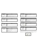
Parameter 2:
HS.H:
Enables or disables the Hot standby function. You may choose one of
the following two options in
Parameter 3:
YES:
Hot standby function is enabled. It means that the current UPS is set to
hot standby so it will restart once electricity is reestablished, even without a
battery connected.
NO:
Hot standby function is disabled.
The UPS is operating in normal mode and therefore it will not restart without
having a battery connected.
Interface
Setting
12: Hot standby function enable/disable
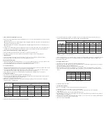
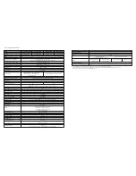
Parameter 2:
Select
Add
or
Sub
function to adjust battery voltage to its
actual reading.
Parameter 3:
The voltage ranges from 0V to 5.7V, the default value is 0V.
Interface
Setting
13: Battery voltage adjustment
Parameter 2:
You may choose
Add
or
Sub
to adjust the charger voltage.
Parameter 3:
The voltage ranges from 0V to 9.9V, the default value is 0V.
NOTE:
*Before making any voltage adjustment, disconnect all batteries first to get the
accurate charger voltage.
*We strongly suggest using the default value (0). Any modification should
match battery specifications.
Interface
Setting
14: Charger voltage adjustment
Parameter 2:
You may choose Add or Sub to adjust the inverter voltage.
Parameter 3:
The voltage ranges from 0V to 6.4V, the default value is 0V.
Interface
Setting
15: Inverter voltage adjustment
Parameter 2:
You may choose Add or Sub to adjust the output voltage.
Parameter 3:
The voltage ranges from 0V to 6.4V, the default value is 0V.
Interface
Setting
16: Output voltage adjustment
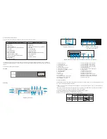
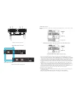
3-8. Operating mode/Status description
When parallel UPS systems are successfully set up, an additional screen with “PAR” in parameter 2 will be displayed and assigned
a number in parameter 3, as shown below. The master UPS will be assigned “001” as default, while the slave UPS units will be
identified as either “002” or “003”. The assigned numbers may be changed dynamically during operation.
Summary of Contents for FDC-106KMR-ISO
Page 17: ......


