background image

2-1. Unpacking and inspection

Remove the UPS from its package and make sure that all the following items are included:

Carefully inspect the UPS to check for any damages that may have occurred during shipping. Should any evidence of damage be 
found or if some parts are missing, do not turn the UPS on; you must immediately notify the carrier or dealer where you purchased 
the unit.

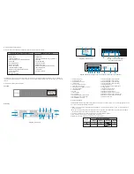
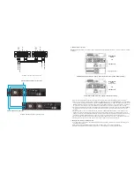
2-2. UPS front and rear panel views


Front view

Rear panel 

2-3. UPS installation

Installation and wiring must be performed by qualified personnel, and in accordance with the local electrical regulations and codes. 
Also, you must observe the following instructions:

1) Make  sure  the  mains  wire  and  breakers in the building are enough for the rated capacity of   UPS  to  avoid the hazards of       
    electric shock or fire.

   Note:

 Do not use a wall receptacle as the input power source for the UPS, as its rated current is less than the UPS maximum          

   input current. Failure to do so may result in a broken or burned out receptacle.
2) For safety considerations, turn off the mains switch in the building before installation.
3) Turn  off  all  the  devices  before  connecting  them  to  the  UPS.
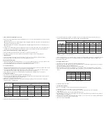
4) Wiring sizes should be installed in accordance with the following table:

16. Isolation transformer output terminals
17. Isolation transformer input terminals
18. Isolation transformer input grounding
19. Isolation transformer output grounding
20. Battery pack ground
21. UPS secondary ground for battery pack
22. Output breaker
23. Maintenance bypass switch
24. Output control signal slot
25. Maintenance bypass ground
26. Maintenance bypass output terminals
27. Maintenance bypass UPS output terminals
28. Maintenance bypass UPS input terminals
29. Utility input terminals

1.   Parallel current port
2.   Parallel data  ports 
3.   External battery connector 
4.   Intelligent slot
5.   RS-232 communication port
6.   USB communication port
7.   Emergency power off (EPO) connector
8.   Input circuit breaker 
9.   Output terminals
10. Ground
11. Input terminals
12. Cooling  fans
13. External maintenance bypass switch
14. Battery pack output circuit breaker
15. External battery connector

Isolation transformer version (110V)

Standard version (220V)

- Online UPS 
- Battery bank 
- Isolation transformer 
- CD with ForzaTracker monitoring software
- USB cable
- One parallel cable
- Share current cable
- Battery pack cable
- Isolation transformer cable
- Rack mounting brackets and hardware 
- Tower support base  
- User manual 
- Warranty certificate

- Online UPS 
- Battery bank 
- CD with ForzaTracker monitoring software
- USB cable
- One parallel cable
- Share current cable
- Battery pack cable
- Rack mounting brackets and hardware 
- Tower support base  
- User manual 
- Warranty certificate

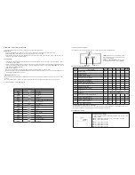
Wiring specification (AWG)

Model

Input

Ground

Output

Battery

6K

10K

10

8

10

8

10

8

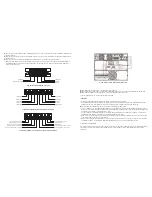
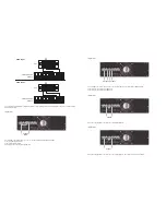
Diagram 1: UPS unit 

Diagram 2: Battery pack

Diagram 3: Isolation transformer

input and output terminals 

Diagram 4: Maintenance bypass switch with breaker input and output terminals

19

16

17

18

15

20

14

BYPASS

LINE

BATT

FAULT

OFF/ESC

TEST/UP

MUTE/DOWN

ON/ENTER

5

6

7

13

4

3

1

2

12

9

10

11

8

21

29

25

26

28

27

25

22

23

24

Summary of Contents for FDC-106KMR-ISO

Page 1: ...2 y e a r W a r r a n t y Ajustes 07_14_2017 User manual Uninterruptible Power Supply System FDC 106KMR ISO FDC 110KMR ISO FDC 206KMR FDC 210KMR...

Page 2: ...he UPS must be thoroughly dry before being installed Failure to do so may increase the risk of electric shock Do not install the UPS system near water or in moist environments To reduce the risk of ov...

Page 3: ...f the UPS system and of all connected loads The UPS system features its own internal current source batteries The UPS output sockets or output terminals block may be electrically live even if the UPS...

Page 4: ...ry ground for battery pack 22 Output breaker 23 Maintenance bypass switch 24 Output control signal slot 25 Maintenance bypass ground 26 Maintenance bypass output terminals 27 Maintenance bypass UPS ou...

Page 5: ...battery pack breaker must also be set to OFF before installing the battery pack Pay close attention to the rated battery voltage marked on the rear panel If you want to change the number of batteries...

Page 6: ...VA load max Connect X1 X3 via jumper wire Connect N N via jumper wire This will give you 120V output for 10KVA load The following connection will give you two sets of 120V outputs each output takes 5K...

Page 7: ...m the selected settings of the configuration menu Turns off the UPS Press and hold this button for 0 5 second to turn off the UPS Esc key Press this button to return to the last setting of the configu...

Page 8: ...e UPS will perform an automatic battery self test on a periodic basis The default setting for the battery self test is once per week 3 Battery self test interval can also be set through the monitoring...

Page 9: ...ixed 11 Operation in fault mode 1 When the Fault LED illuminates and the buzzer beeps continuously it means that there is a fatal error in the UPS Fault codes are available via the LCD panel Refer to...

Page 10: ...re connected correctly 4 Turn on each UPS one by one and make sure that AC mode LED or Battery mode LED display is lit in each UPS Using a multimeter measure the output voltage of each UPS to make sur...

Page 11: ...he load and complete ly shut down the UPS system 2 Enable the Bypass setting in each UPS and then power off the running UPS All UPS units in the parallel system will transfer to Bypass mode Remove all...

Page 12: ...ce Setting 03 Voltage range for bypass Parameter 3 Frequency mode Enables you to set the output frequency in either CVCF mode or no CVCF mode You may choose any of the following two options in paramet...

Page 13: ...V to 5 7V the default value is 0V Interface Setting 13 Battery voltage adjustment Parameter 2 You may choose Add or Sub to adjust the charger voltage Parameter 3 The voltage ranges from 0V to 9 9V the...

Page 14: ...ress This operation is used to check the battery status 3 9 Fault codes 3 10 Warning indicators Fault event Bus start failure Bus over Bus under Bus unbalanced Inverter soft start failure High inverte...

Page 15: ...UPS is overloaded UPS is overloaded Devices connected to UPS are fed directly with utility power through Bypass After repetitive overloads the UPS is locked in Bypass mode Connected devices are fed di...

Page 16: ...utput Nominal voltage AC voltage regulation battery mode Frequency synchronized range Frequency battery mode Power factor Efficiency AC mode Efficiency battery mode Overload Transfer time line to batt...

Page 17: ......

Reviews: