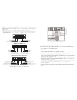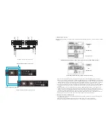
L
N
L
N
Ground
L
N
L
N
Ground
Input neutral
Input line
Output neutral
Output line
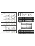
Diagram 1: Power cable connection
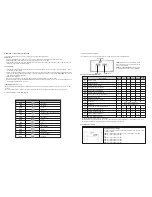
Parallel communication port connection
Share current cable connection
Diagram 2: Wiring diagram of parallel system
2. Parallel system connection
NOTE:
For parallel installation each UPS must have a maintenance bypass output breaker/switch connected. This device is offered
separately.
1) Once you have verified all wiring has been done properly, turn off the input, output and battery breakers of each UPS.
2) Remove all the maintenance bypass covers and change the maintenance switches from
UPS
to
BPS
, turn on the input breaker
of the each UPS and change the maintenance switches from
BPS
to
UPS
. When done, replace the maintenance bypass cover.
With a multimeter, measure the L1-N1 and L2-N2 voltage difference between each UPS. If the voltage difference is less than
2V, it means all connections are correct. If the difference is higher than 2V, check if the wiring has been done correctly.
3) Turn on the input breakers of each UPS in the parallel system. Before turning on each UPS in turns, check if PAR001~PAR003
are displayed in each UPS sequentially. If no “PARXX exists in any UPS, please check if the parallel cables are connected
correctly.
4) Turn on each UPS one by one and make sure that AC mode LED or Battery mode LED display is lit in each UPS. Using a
multimeter, measure the output voltage of each UPS to make sure the voltage difference is less than 2V (typical 1V). If the
difference is above 2V, check that parallel cables and/ or parallel current cables are connected properly. If all connections are
done properly, it may be a UPS internal issue. In this case, contact your local distributor or service center for help.
5) Turn off each UPS in sequence. After all of the UPS are transferred to Bypass mode, turn on the output breaker of each unit.
6) Finish by turning on the UPS units in AC mode. Now the system is ready for operation in parallel mode.
3. Adding one new unit into the parallel system
1) You cannot add one new unit into the parallel system while the whole system is running. First, all loads and each UPS in the
system must be shutdown.
2) Make sure all of the UPS are parallel models, and follow the wiring scheme shown earlier in this manual.
3) Install the new UPS and follow instructions in the previous section for proper connection, testing and startup.
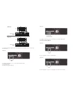
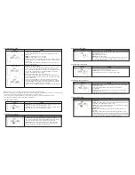
Full installation with maintenance bypass and isolation transformer (110V or 220V operation)
MAINTENANCE
BYPASS
UPS
BATTERY PACK
ISO (Output to load)
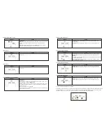
Full installation with maintenance bypass (220V operation only)
MAINTENANCE
BYPASS
(Output to load)
UPS
BATTERY PACK
Output load
Ground
Summary of Contents for FDC-106KMR-ISO
Page 17: ......


