


03·01A·16
Engine, 3.8L
03·01A·16
IN-VEHICLE SERVICE (Continued)
Heater Water Inlet Hose Removal
__..-
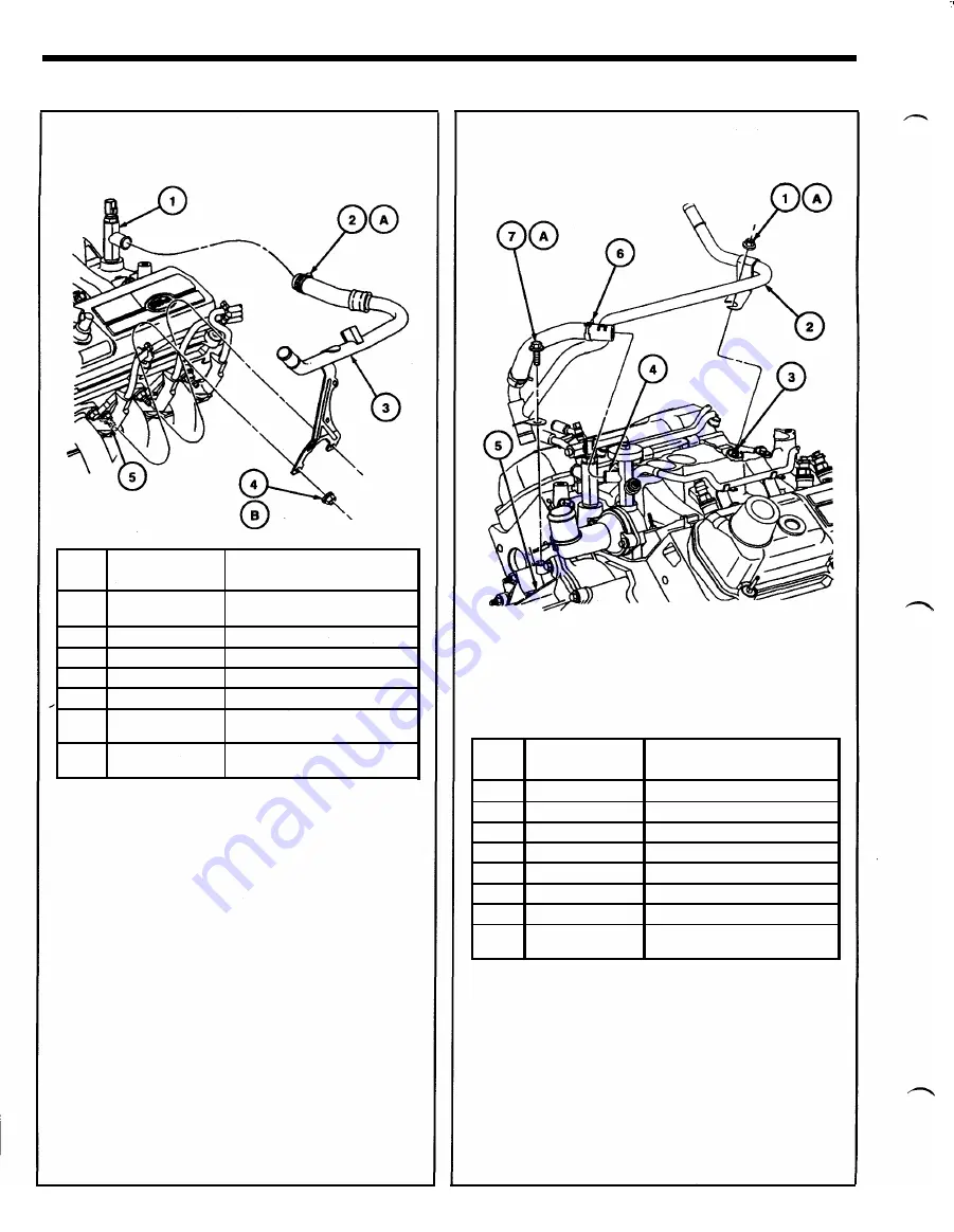
FRONT OF ENGINE
-----
A24822·A
P
ar
t
Item
Number
Description
1
18599
Hot Water Heater Elbow
Connection
2
-
Clamp
3
18472
Heater Water Hose
4
N62 1939
Nut (2 Req'd)
5
9430
Exhaust Manifold, RH
A
-
Tighten to 2.5-3.5 N·m (23-30
Lb-ln)
B
-
Tighten to 20-30 N·m ( 15-22
Lb-Ft)
Heater Water Outlet Hose Removal
----
FRONT OF ENGINE
----
NOTE: LUBRICATE HEATER WATER OUTLET
TUBE ASSY
"0"
RING OR BORE WITH
ESE·M99B144-B SURFACTANT PRIOR TO
INSTALLATION
P
a
rt
Item
Number
Description
1
N807609
Nut
A24823·A
2
1 8663
Heater Water Outlet Tube
3
-
Lower Intake Manifold Stud
4
8A530
Water Bypass Tube
5
8501
Water Pump
6
-
Clamp
7
N606676
Bolt
A
-
Tighten to 8- 1 1 N·m 7 1 -97
(Lb-ln)
5.
Remove heater water outlet hose.
6. Remove lower intake manifold retaining
bolts/studs.
7.
CAUTION: The lower intake manifold is
sealed at each end with silicone sealer. To
break the seal, it may be necessary to pry on
the front of the lower intake manifold with a
prybar. If it is necessary to pry on the lower
intake manifold, use care to prevent damage
to machined surfaces.
Remove lower intake manifold.
1 997 Thunderbird, Cougar July 1 996


