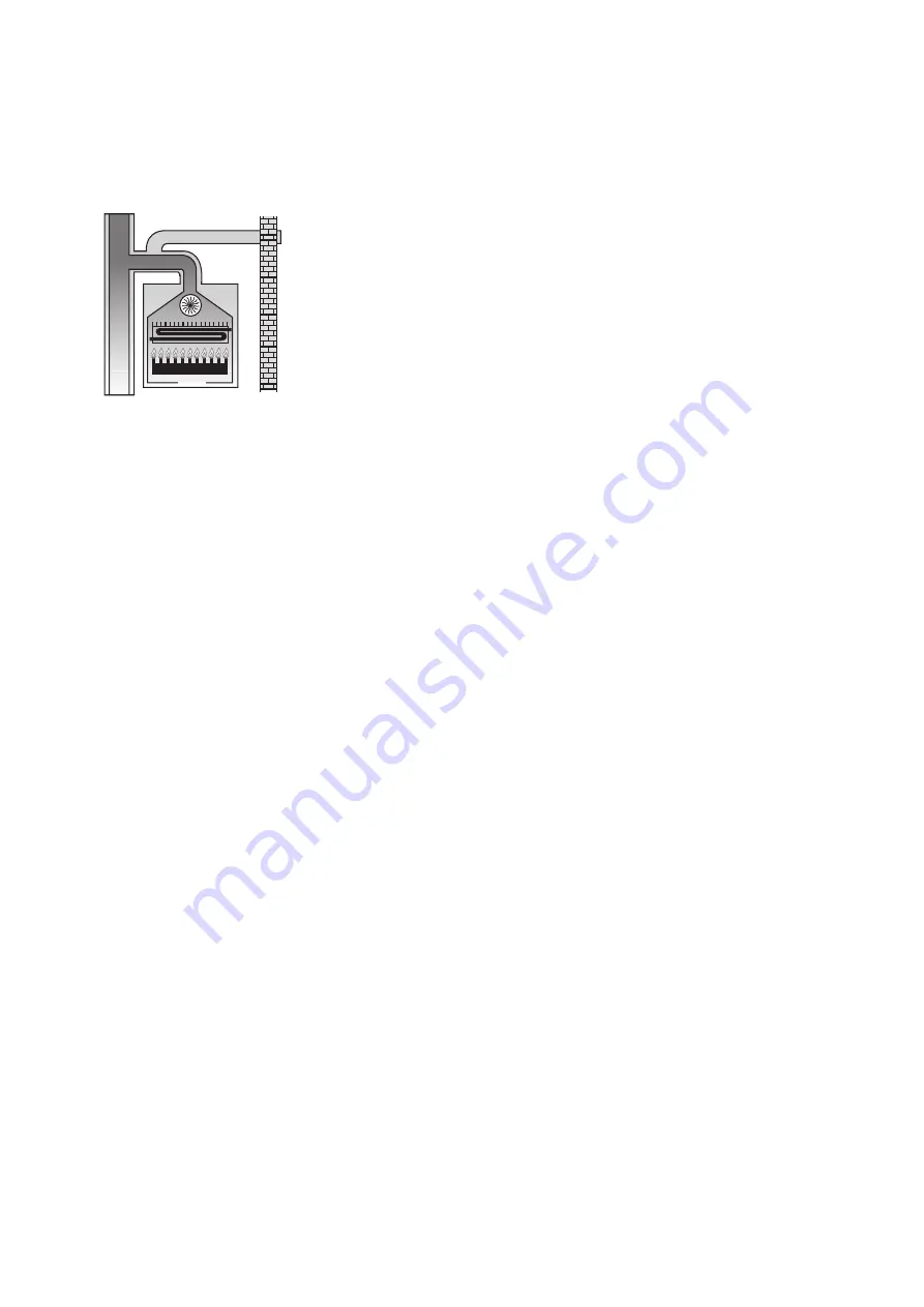
- Model
RTFS 32
and
RTFS 36
: for
installations with an equivalent
length of less than 2+2 metres,
install a 42 mm diaphragm on the air
intake.
Type C82
This boiler is designed to be con-
nected to a terminal for taking in
combustion-supporting air and an
individual or collective smoke flue.
The smoke flue is to comply with
current standards.
• Air intake/smoke flue double 80
mm diameter piping
Configuration allowed for maximum
distance:
N° 2 flanged stub pipes
N° 4 metres of air intake piping
N° 1 metre of smoke flue piping
N° 1 air intake terminal
Notes:
- 1,6 metres of air intake piping is
equivalent to 1 metre of horizon-
tal smoke flue piping.
- Reduce the maximum length by 1
metre for each 90° bend.
- Reduce the maximum length by
0,5 metres for each 45° bend.
- Models
RTFS 18
and
RTFS 24
:
install a 42 mm diaphragm on the air
intake.
- Model
RTFS 32
and
RTFS 36
:
install a 40 mm diaphragm on the air
intake.
3.2.6 On site measurement of
combustion performance
To determine combustion perfor-
mance the following measurements
must be taken:
• The temperature of the combu-
stion-supporting air.
• The temperature of the smoke and
the percentage of CO
2
in samples
drawn from the hole provided for this
purpose in the smoke duct.
Taking the specific measure-
ments with the boiler running at
normal load.
3.2.7 Connecting to the gas mains
The gas supply pipe is to have a
cross-section that is equal to or
greater than that on the burner.
Installation standards must be com-
plied with and are taken as being an
integral part of this booklet.
Remember that before putting an
internal gas distribution system
into service, before it is connec-
ted to the meter, it must be chec-
ked for leaks.
If any part of the system is inac-
cessible the leak test must be car-
ried out before the pipes are
covered up.
The leak test must not be carried
out using combustible gas. Use
air or nitrogen for this purpose.
Once there is gas in the pipes,
checking for leaks using a naked
flame is forbidden.
Use the products made for this
purpose that are available on the
market.
3.2.8 Connecting to the electricity
power supply
BALI boilers have a terminal board for
connecting up a three-pole power
supply cable, and a suitable cable
clamp to prevent it being torn out.
This boiler must be connected to a
230V-50Hz
electrical power supply.
When forming the connection
respect the phase/neutral polarity.
Installation standards must be com-
plied with and are taken as being an
integral part of this booklet.
A two-pole switch must be fitted
upstream of the boiler to allow all
maintenance work to be carried out
in complete safety.
The power supply to the boiler must
be fitted with a differential magnetic-
thermal trip-switch of a suitable trip-
ping power.
The electrical power supply must be
safely earthed.
This basic safety requirement must
be checked. In case of doubt, call in
professionally qualified personnel to
check the electrical system carefully.
FONDITAL accepts no responsi-
bility whatsoever for any damage
caused due to failure to earth the
system. Piping for gas, plumbing,
or heating systems are not suita-
ble for earthing this system
.
3.2.9 Plumbing Connections
Before installation the system
should be cleaned in order to remo-
ve the impurities that may come
from the components as far as pos-
sible, as these could damage the cir-
culation or heat exchange units.
The heating feed and return pipes
must be connected up to the respec-
tive couplings on the boiler.
When sizing the piping for the hea-
ting system, bear in mind the load
losses caused by radiators, thermo-
static valves, radiator gate valves,
and the configuration of the system
itself.
3.2.10 Installation of original kits
FONDITAL
provides original kits for
installing clock programmers, cards
for managing a remote boiler, and
for installing a heat-regulating unit.
These original kits are to be installed
in compliance with the instructions
supplied with them.
3.3 Filling the system
Once all the connections in the
system have been completed, the
heating circuit can be filled.
This must be carried out carefully,
and in the following steps:
• Open the bleeding valves on the
radiators and make sure that the
vent valve installed in the boiler
room is working.
• Gradually open the relevant stop-
cock to fill the system and make
sure that all automatic air vents
installed in the system are working
properly.
• Close the vent valve as soon as
water comes out of it.
• Use the pressure gauge installed
in the boiler room to check when the
pressure reaches 0,8 / 1 bar.
• Shut the filling stopcock and bleed
any air out again using the bleeding
valves on the radiators.
11


