background image

16

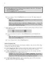
Recording charge data

The Charge Control Software can record charge data for each charging session. 
1.  Press the 

Start/Stop

 button on the charger to start a session.

2.  When prompted, enter a file name.  You can enter a file name you previously used, but you 

must confirm that you want to overwrite older data.

Charge data is stored in a semicolon-delimited format, which can be imported into a spreadsheet 

for analysis.

Updating charger firmware

The Charge Control Software automatically checks for new firmware each time it is launched (as

-

suming the computer is connected to the Internet).  If new firmware is available, it is downloaded 

to your computer.  When you are ready to update the charger:
1.  Be sure the charger is connected to the computer, and is powered up.
2.  Disconnect all packs from the charger.
3.  In the Charge Control Software window, switch to the 

Firmware

 tab.

4.  Select the firmware you want to download.
5.  If the previous firmware download was interrupted, activate the 

My Charger is Dead

 option.

6.  Click Update Firmware.
7.  Wait—and do nothing—until updating is complete.

IMPORTANT:

  During firmware downloading, do not disconnect the charger from power, 

do not disconnect the charger from the computer, and do not exit the Charge Control 

Software.

Node connector wiring

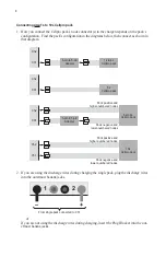
This diagram shows how a 6 pin node connector is wired to a 5s pack.

Pin 1

Red

Black

Pack positive
Node 4

Node 2

Node 3

Node 1
Pack negative

Cell 4

+

Cell 3

+

Pack negative 

(blk), 0V

Node 3, 11.1V*

Node 4, 14.8V*

Cell 5

+

Pack positive 

(red), 18.5V*

Cell 2

+

Node 2, 7.4V*

5s Pack

Cell 1

+

Node 1, 3.7V*

*  Nominal voltage with 

respect to pack negative.

Summary of Contents for Revolectrix Cellpro 10s

Page 1: ...al cell internal resistance to 0 1milliohm an exclusive feature for estimating pack quality and finding bad cells Backlit LCD display provides easy readability Bidirectional PC interface enables extensive charger setup using free Charge Control Soft ware Configure custom presets adjust speaker volume set LCD contrast and control many other settings Charge Optimization can be set for an accurate 1m...

Page 2: ...ge Control Software Charger and pack terminology Mode button Start Stop button Channel 1 node connector Channel 2 node connector Banana jacks for discharge wires when charging one pack or insert Plug Blocker when not charging through discharge wires Banana jacks for discharge wires when charging two packs at the same time To power source Auto mini fuse Connect FUIM2 here when using Charge Control ...

Page 3: ...harger beeps three times The pack can be removed to use or allowed to continue charging until the pack is 100 full and the charger displays Charge Complete During the entire charge process the charger power balances the pack using 1A current until all cell voltages are within 1mV of each other Power balancing is the process of beginning the balancing process early in the charge cycle using high cu...

Page 4: ...r to remove the pack from the charger and continue charging the 5000 mAh pack at a higher charge rate Here s the full procedure 1 Connect both packs and start charging them at an Auto rate 2 Watch the fuel level display When one pack reaches 99 fuel level the charger beeps three times stop charging 3 Disconnect the full pack 4 If the partially charged pack is connected to Channel 2 move it to Chan...

Page 5: ...nana plugs suitable for this purpose as FMA Part Numbers BPNS BLK Black and BPNS RED Red CAUTION When using the banana plug adapter cables described above ALWAYS insert the banana plugs into the charger BEFORE connecting the adapter cable to the pack Reverse the sequence when disconnecting the pack This will prevent the live banana plugs from touching each other which would create a dangerous cond...

Page 6: ...discharge wires into the outermost banana jacks or If you are not using the discharge wires during charging insert the Plug Blocker into the out ermost banana jacks 6 pin to 5 pin Adapter 1s to 4s Cellpro pack Ch2 Ch1 5s Cellpro pack Ch2 Ch1 6 pin to 5 pin Adapter 6s to 9s Cellpro pack Pack positive and higher numbered nodes Pack negative and lower numbered nodes Ch2 Ch1 10s Cellpro pack Pack posi...

Page 7: ...ect the discharge wires into the ba nana jacks as shown below or If you are not using the discharge wires during charging insert the Plug Blocker into the out ermost banana jacks Ch2 Ch1 6 pin to 5 pin Adapter 1s to 4s Cellpro pack 6 pin to 5 pin Adapter 1s to 4s Cellpro pack Ch2 Ch1 5s Cellpro pack 6 pin to 5 pin Adapter 1s to 4s Cellpro pack Ch2 Ch1 5s Cellpro pack 6 pin to 5 pin Adapter 1s to 4...

Page 8: ...power is applied the charger always initializes to the last preset used for charging In structions in Selecting a preset later in this manual show how to switch between these presets If you altered the charge settings for a preset at the charger as described in Changing a preset later in this manual those changes are retained when the charger is disconnected from power and will be reapplied when t...

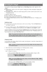
Page 9: ...ode button is the selected preset Once the preset is selected you can change the charge settings for this preset see Changing a preset or begin charging by pressing the Start Stop button Note The Charge Control Software enables you define up to six custom presets If you have defined custom presets you can at the charger select any preset If you have not defined custom presets the two factory prese...

Page 10: ...ach of the following three Auto charge modes or Storage charge mode 1 0C where C pack s capacity 2 0C 3 0C Store to charge pack to about 50 capacity optimum for long term storage Return to charge current settings at 0 1A Note The charger s Auto charge fuel gauge tables are optimized for Lithium Cobalt batteries If you are charging Lithium Manganese batteries Auto charge modes may take twice as lon...

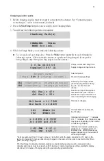
Page 11: ... first cell in the pack connected to Ch1 and n is the last cell in the pack if only one pack is being charged or the last cell in the pack connected to Ch2 if two packs are being charged For the charger to calculate internal resistances a pack discharge wires must be connected during charging and b pack must be at less than 80 fuel level Internal resistances will be available for display after abo...

Page 12: ...nate charging modes Based on what the charger determines about charging conditions it may enter one of these charg ing modes as indicated in the display In Low Voltage Restore Mode the charger automatically attempts to repair an overdischarged pack Cells discharged as low as 0 5V may be repaired to as much as 98 of capacity In Safety Charging Mode the charger detects that at least one cell is seri...

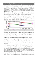
Page 13: ...l Software 1 Start All Programs FMA Direct Cellpro 10s 2 If your computer is connected to the Internet at this time the program will check to see whether a new version is available If a new version is available you will have the option to install the new version or launch the version you already have 3 After the program launches and if your computer is connected to the Internet the program will ch...

Page 14: ...es that the power supply can t keep up You can also manually limit the charger s input current so the charger will not draw more power than the supply can provide If you know your power supply is rated for 3A output for example you can limit the charger s input current to 3A This feature prevents damage to power supplies such as bench supplies having low to moderate output currents Be aware that l...

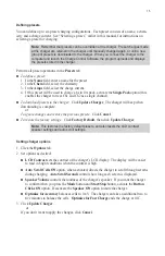
Page 15: ...pdate Charger The charger will beep when downloading is complete or To ignore changes and restore the previous presets Click Cancel To restore the factory settings Click Factory Default then click Update Charger Note This restores the factory default presets and also resets the LCD contrast speaker settings and auto scroll settings Setting charger options 1 Click the Options tab 2 Set options as d...

Page 16: ...ure the charger is connected to the computer and is powered up 2 Disconnect all packs from the charger 3 In the Charge Control Software window switch to the Firmware tab 4 Select the firmware you want to download 5 If the previous firmware download was interrupted activate the My Charger is Dead option 6 Click Update Firmware 7 Wait and do nothing until updating is complete IMPORTANT During firmwa...

Page 17: ...ing flight A x Average current during flight V Average power during flight Watts Evaluate results n Average current during flight gives you a rough idea whether system components ESC motor connectors and wiring are operating within their current ratings Keep in mind that peak current during flight may greatly exceed the average current you calculated n Watts per pound is an approximate indicator o...

Page 18: ...annot be determined check for a cell 0 5V Ch1 has no Pack Pack must be installed on Ch1 Ch1 No Add Up Cell verification failed Ch1 Pos 0 5V Check node wiring Ch2 Bad S Count Cell count cannot be determined check for a cell 0 5V Ch2 No Add Up Cell verification failed Charger Overcurrent Make sure the charger current is steady Check Pos Term Positive terminal not connected Chg Overvoltage Cell is ov...

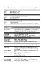
Page 19: ...d to 1A to 25A in 0 25A increments Power conversion 62 5kHz switcher operating at 90 efficiency Nominal output voltage 3 60 4 10 and 4 20 volts per cell 42V maximum Output current Up to 3A reverse polarity protected Cell balancing To within 1mV with 0 1mV resolution Voltage calibration Cell voltage measurements are factory calibrated to 1ppm 50μV traceable to NIST Internal switches Four internal F...

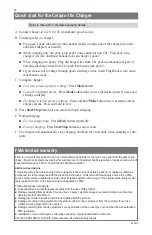
Page 20: ... than an authorized FMA technician Installation or removal charges or damage caused by improper installation or removal Call 301 668 4280 for more information about service and warranty repairs Quick start for the Cellpro 10s Charger Refer to manual for complete operating details A Connect charger to a 12V to 16V maximum power source B Connect pack s to charger n Plug pack s node connector s into ...

Reviews: