4
utes at 3C. However, if the packs have different capacities, or were discharged to different levels,
charging for the pair could take longer than expected. Since the charger supports fast balance cur-
rent of 1A, all other things being equal, the charger still outperforms competing brands. In most in-
stances, by the time the first pack is fully charged, the second pack is already approaching constant
voltage charge mode; the battery pack itself is the limiting factor in charge time, not the charger.
Example 1:
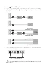
You are powering an aircraft with two 4s 2100mAh packs connected
in series. Because those packs have the same capacity, and were discharged to
about the same level, you can expect them to charge in about the same time. It
would be appropriate to charge them simultaneously using the Cellpro 10s Charger.
Example 2:
You are powering one aircraft with a 3s 500mAh pack, and other air-
craft with a 5s 5000mAh pack. If you charge these packs simultaneously using the
Cellpro 10s Charger, it would probably take a long time (the 500mAh pack would
become full first, then the charger would switch to its 1A balancing rate to fill up
5000mAh pack, which could take several hours). In this case, it would be faster
to charge these packs separately because the charger can then apply optimum (and
substantially different) charge currents to each pack.
In some cases, such as Example 2, it will be faster to charge two packs separately rather than
simultaneously. It’s up to you to decide whether to charge two packs individually or as a pair,
based on what you know about their respective capacities and discharge states.
The Cellpro 10s is equipped with FMA Fuel Gauging technology. During all phases of the
charge process, the charger will report the fuel level of two packs being charged independently.
In Example 2 above, when the 500 mAh pack reaches 99% capacity (the charger beeps three
times), it is a simple matter to remove the pack from the charger and continue charging the 5000
mAh pack at a higher charge rate. Here’s the full procedure:
1. Connect both packs and start charging them at an Auto rate.
2. Watch the fuel level display. When one pack reaches 99% fuel level (the charger beeps three
times), stop charging.
3. Disconnect the full pack.
4. If the partially charged pack is connected to Channel 2, move it to Channel 1.
5. Continue charging the partially-charged pack.
Charger input current limiting
The charger will draw up to 25A to deliver its 10A maximum output current. The high input current
is required when the input voltage must be boosted to drive packs having larger numbers of cells
in series. The charger’s algorithms are based on power, not current. The charger initially draws
300W, but will automatically reduce power consumption based on its internal temperature. Output
power is determined by several factors, including battery pack imbalance during charge, input volt-
age, input current, output voltage, ambient temperature, and the charger’s internal temperature.
The charger’s DC-to-DC converter is typically 80% to 90% efficient. Highest efficiency occurs
when the input voltage is higher than the output voltage needed to charge the connected pack(s).
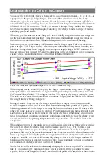
However, the charger cannot tolerate input higher than 16V. Setting the input voltage to 15V pro-
vides the highest efficiency, coolest operating temperature and fastest charging times, especially
when charging packs containing more than five cells in series.
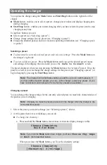
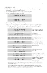
You can also manually limit the charger’s input current so the charger will not draw more power
than the supply can provide. If you know your power supply is rated for 3A output, for example,
you can limit the charger’s input current to 3A. (Be aware that limiting charger input current
may increase pack charge times.) When the charger is powered from a high current source (such
as a car battery), you can override manual current limiting to provide maximum pack charging
current. Details are provided in “Limiting charger input current” in the “Using the Charge Con-
trol Software” section of this manual.


