


™/S, MOLBLOC TERMINAL OPERATION AND MAINTENANCE MANUAL
© 1995 - 2010 Fluke Corporation, DH Instruments Division
Page 160
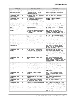
SYMPTOM
PROBABLE CAUSE
SOLUTION
Flow indication appears to be
incorrect and molbloc is upstream
and reading high.
Leak downstream of molbloc.
Check for and correct leak if present.
Consider using SYSTEM LEAK
CHECK function. 3..4.3
Flow indication appears to be
incorrect and flow rate is less than
50 sccm.
Flow in system is not in steady state;
too much volume between molbloc and
test; unstable pressure on molbloc.
Be sure flow is stable before reading, reduce
dead volumes, install precision regulator,
consider using
DHI
low flow molstic.
Flow indication appears to be
incorrect and flow unit is a
volumetrically based mass flow
unit (sccm, scfh, etc.).
Reference temperature or
compressibility consideration in
volumetrically based units is
inconsistent.
Set units correctly for consistency between
values being compared. Be sure to select a
unit starting in “u” for volumetrically based
mass flow units if reference temperature is
not 0
°
C. 3.4.3, 3.4.3.3
Unable to make molbloc-S flow
measurements over full expected
flow range
MFC or flow control valve is connected
dowsntream of molbloc-S
Valve or regulator used to control flow
through molbloc-S must always be upstream
of the molbloc-S. When operating an MFC
with molbloc-S, the MFC must always be
upstream.
Unable to make molbloc-S flow
measurements over full expected
flow range
molbloc-S back pressure too high
The downstream pressure on molbloc-S must
always be significantly lower than the
upstream pressure to maintain critical flow.
When upstream pressure is reduced, the
back pressure ratio may become too high to
make valid flow measurements. 3.1.5
Unable to make molbloc-S flow
measurements over full expected
flow ranges.
Flow units use reference temperature
other than 0° C.
The molbloc-S flow range tables display flow
ranges expressed in slm @ 0° C. If you use
volumetrically based flow units with another
reference temperature, the minimum usable
flow value may be increased by up to 9% for
a given molbloc-S downstream pressure.
1.2.5.2.1, 3.4.3.3, tables 4 to 14
Unable to reach molbloc-S
maximum flow
Pressure regulator supplying molbloc-S
set too low.
If you are controlling flow with a control valve
downstream of a fixed pressure regulator,
you must have sufficient pressure supply
pressure to reach the maximum desired
molbloc-S flow. Be sure not to exceed
maximum operating pressure.
1.2.5, 2.3.4
Flow indication appears to be
incorrect and flow unit is a volume
(actual) flow unit (ccm, cfh, etc.).
Volume flow pressure and/or
temperature is/are incorrect.
Set more accurate values for volume flow
pressure and/or temperature. 3.4.3.1, 3.4.3.4
Flow indication appears to be
incorrect and there is a K following
the flow unit on the display.
A K factor is being applied incorrectly or
inadvertently.
Turn off or correct K factor. 3.4.1
Flow indication appears to be
incorrect and you are using
AVERAGING function.
Averaging period is wrong and does not
correspond to reading period of the
device you are comparing with.
Adjust averaging period and/or be sure to
synchronize averaging period of the
and the device you are comparing
to. 3.4.6.2
Flow indication is negative.
Flow in your system is reverse from
what you expect; molbloc upstream and
downstream pressure lines are
switched.
Check system and correct flow; check
pressure lines and switch if necessary.
Pressure transducer (RPT)
indications are out of range.
Incorrect RPT calibration coefficients;
RPT(s) has (have) been overpressured.
Correct calibration coefficients; have
transducers replaced if damaged. 5.2
molbloc-S Tare does not execute
as expected
Expectation of tare function operation is
incorrect for molbloc-S.
Normal operation. The molbloc-S
tare function has a different purpose and
method of operation from molbloc-L tare and
does not require saving a fixed tare value.
3.4.4.1.2
Cannot
tare
molbox due to
excessive
tare
value.
One or several RPTs are defective;
RPT calibration is bad; there is a leak
inside causing a differential
pressure.
Check performance of RPTs; check
calibration of RPTs; leak check .
5.2