


™/S, MOLBLOC TERMINAL OPERATION AND MAINTENANCE MANUAL
© 1995 - 2010 Fluke Corporation, DH Instruments Division
Page 62
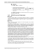
When
[ENTER]
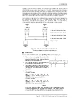
is pressed, ’s valves actuate to set up the system leak
check configuration which is identical to the normal operating configuration
(see Figure 3). The display becomes:
1.
Pressure read by the upstream RPT (left), the
downstream RPT (right) and the pressure unit of
measure (middle).
2.
Current measured flow.
3.
Time remaining in the leak check in seconds.
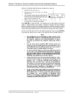
347.592 kPaa 47.583
0.101 sccm 30
measures pressure and flow for a 40 second countdown. After the
countdown has elapsed, displays its conclusion from the
measurements. The display will be either:
possible system
upstream leak
Or
possible system
downstream leak
Or
System passed system
leak check
Upstream and downstream refer to the possible location of the leak relative to the
position of the molbloc and the normal flow direction in the system. If you are
unable to locate a leak in the flow path components, check or replace the
upstream and downstream molbloc to molbox pressure tubes and their connectors
and retry the test. They are a critical part of the pneumatic system and if a significant
leak is present in these tubes, it will cause an error in flow measurement.
OPERATION – molbloc-S Operation
In molbloc-S operation, SYSTEM LEAK CHECK is a one-part test which tests for
pressure decay in the closed system.
To access the system leak check press
[TARE]
and select
<3leak check>
,
<2system>
.
The display is:
Leak check:
1run 2view
If
<2view>
is selected the test results screen (see below) is displayed with the
results from the most recent leak test.
To run the leak test, select
<1run>
.
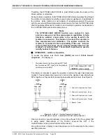
actuates internal valves to connect the upstream and downstream
RPTs together, so they are both measuring an equal system pressure. (see
Figure 10).