Scan/Monitor, Record, and Data
Scan
4
4-3
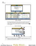
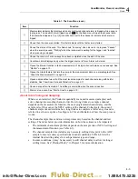
Table 4-1. The Scan Menu (cont.)
Item Function
Master alarm indicator that displays when any configured channel alarm is tripped while a scan is
in progress. To see which alarm tripped, push
on the Scan menu to open the channel data.
If an alarm has tripped, a [1] or [2] icon will show next to the channel to indicate which alarm is
tripped.
Shows then the scan was started. This field is blank until the first scan is started.
Shows the status of the scan. This field shows “Scanning” when a scan is in progress, "Paused"
when the scan is paused, "Waiting" when the Instrument is waiting for the trigger, and “Inactive”
when scanning is stopped.
Shows the number of scan sweeps have been completed since the start of the scan.
Countdown timer displayed only when the trigger source is Timer, Alarm or External.
Opens the Monitor function to take measurements of a single channel between scan sweeps. See
“Monitor” on page 4-13.
Opens the Graph feature that lets the user plot the measurement data on a scalable graph. See
“Graph the Measurements” on page 4-12.
Opens a spreadsheet view of all the most recent samples for each channel along with helpful
statistics. See “View Scan Data and Statistics” on page 4-11.
Pause a scan after it is started. The softkey is not visible when the scan is inactive.
Start or stop a scan. See “Start a Scan” on page 4-10.
About Scan Timing and Sampling
When a scan is started, the Product sequentially scans and measures (samples) each
active channel in ascending channel order. How long it takes to sample a channel
depends on the measurement function, the user-programmed channel delay, and the
sample rate of the scan or the NPLC setting of the channel. Collectively, the sum of
channel sample times determine how long it takes to complete a full scan cycle and is
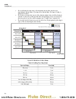
referred to as the sweep time. See Figure 4-2 for an illustration of how the scan process
works.
The channel sample times and scan sweep times vary based on the channel and test
settings. The items below provide information on how these times can be impacted:
•
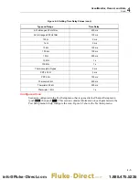
The minimum channel sample time depends on the sample rate or NPLC setting and
the measurement function (see Table 4-3).
•
The channel sample time includes any necessary settling delay prior to the ADC
sample to meet accuracy specifications in usual conditions. Table 4-4 lists the
internal fixed settling delays for each parameter type and range.
•
In some conditions, it may be necessary to add channel delay to allow for longer
settling times. See “Channel Delay” in Chapter 3 for more information.
1.888.475.5235
Fluke-Direct
.com


