

Electrical
Installation
Tester
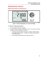
Making
Measurements
25
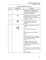
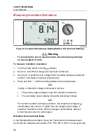
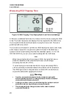
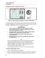
Warning
The symbol
on the LCD indicates the high current loop
mode - any RCDs in the system will trip - ensure there are no
RCDs present.
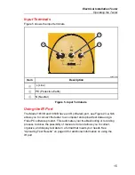
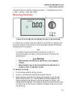
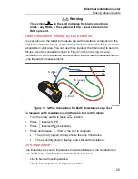
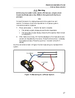
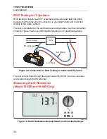
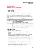
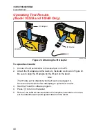
Earth Resistance Testing by Loop Method
You can also use the tester to measure the earth resistance component of the
total loop resistance. Check your local regulations to determine if this method is
acceptable in your area. You can use three leads or the mains cord to perform
this test. Use the connection shown in Figure 13 when making a 3-wire
connection for earth resistance loop test. Zero the test leads (see sequence for
Loop Impedance measurement).
L
N
PE
PE (Green)
L (Red)
N
(Bl
u
e)
apx024f.eps
Figure 13. 3-Wire Connection for Earth Resistance Loop Test
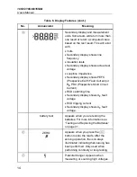
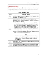
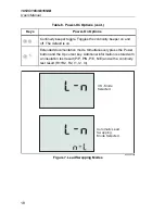
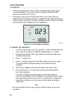
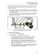
To measure earth resistance using the loop test no trip mode:
1. Turn the rotary switch to the
position.
2. Press
to select L-PE.
3. Press
to select RE (resistance).
4. Press and release
. Wait for the test to complete.
•
The primary (upper) display shows the loop impedance.
•
The secondary (lower) display shows the earth resistance.
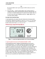
Line Impedance
Line impedance is source impedance measured between Line conductors or
Line and Neutral. This function allows the following tests:
•
Line to Neutral loop impedance.
•
Line to Line impedance in 3-phase systems.


