

Electrical
Installation
Tester
Making
Measurements
21
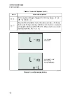
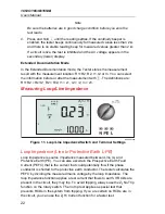
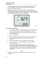
information before or after the measurement with
. The definitions are: P/P =
L, P/N = L-N, P/E = L-PE, N/E = N-PE.
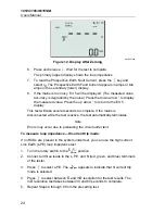
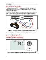
Measuring Continuity
R
LO
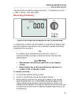
apx003f.eps
Figure 10. Continuity Zero Display/Switch and Terminal Settings
A continuity test is used to verify the integrity of connections by making a high
resolution resistance measurement. This is especially important for checking
Protective Earth connections.
Note
In countries where electrical circuits are laid out in a ring, it is
recommended that you make an end-to-end check of the ring at the
electrical panel.
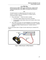
Warning
•
Measurements should only be performed on de-energized
circuits.
•
Measurements may be adversely affected by impedances or
parallel circuits or transient currents.
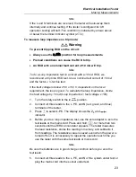
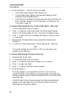
To measure continuity:
1. Turn the rotary switch to the R
LO
position.
2. Use the L and PE (red and green) terminals for this test.
3. Before making a continuity test, use the Zero adapter to zero the test
leads. Press and hold
until the ZERO annunciator appears. The
tester measures probe resistance, stores the reading in memory, and
subtracts it from readings. The resistance value is saved even when power
is turned off so you don’t need to repeat the operation every time you use
the instrument.